30 506 01 2303 01
Specifications are subject to change without notice.
1/2-20 UNF RH
30°
0.596
.47
5/8” HEX
SEAT
CORE
WASHER
DEPRESSOR PER ARI 720
+.01/-.035
FROM FACE OF BODY
7/16-20 UNF RH
O-RING
45°
1/2" HEX
This surface provides a metal to metal seal when
torqued into the seat. Appropriate handling is
required to not scratch or dent the surface.
(Part No. EC39EZ067)
C08453
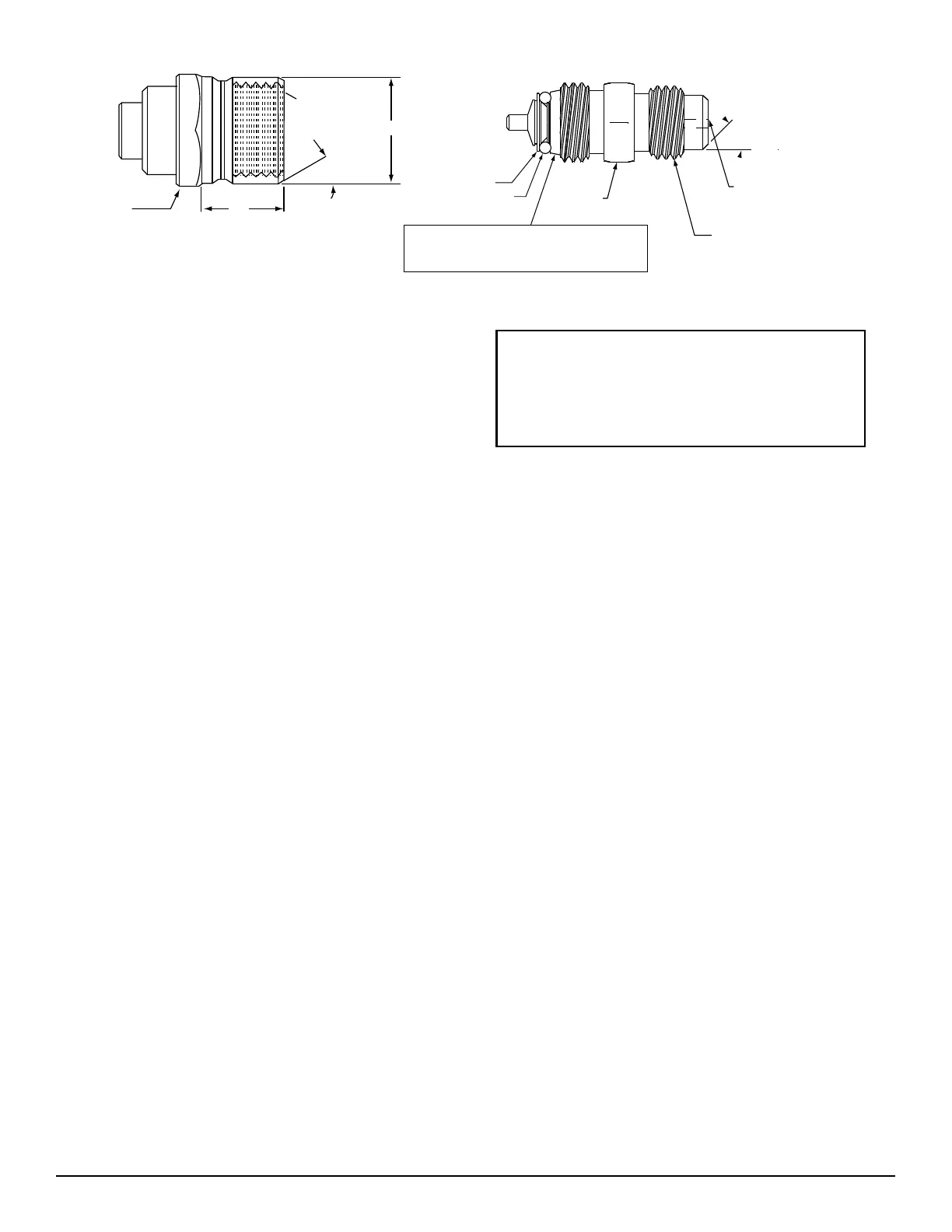
Fig. 23 -- CoreMax Access Port Assembly
Refrigerant System Pressure Access Ports —
There are two access ports in each circuit - on the suction
tube near the compressor and on the discharge tube near
the compressor. These are brass fittings with black plastic
caps. The hose connection fittings are standard 1/4 SAE
Male Flare couplings.
The brass fittings are two-piece High Flow valves, with a
receptacle base brazed to the tubing and an integral
spring-closed check valve core screwed into the base. (See
Fig. 23.) This check valve is permanently assembled into
this core body and ca nnot be serviced separately; replace
the entire core body if necessary. Service tools are
available from RCD that allow the replacement of the
chec k valve core without havi ng to recover the entire
system refrigerant charge. Apply c ompressor refrigera nt
oil to the check valve core’s bottom o-ring. Instal l the
fitting body with 96 +/-10 in-lbs of torque; do not
overtighten.
Compressor Protection
Compressor Overcurrent —
The compressor has internal limbered motor protection.
Compressor Overtemperature Protection (IP) —
The compressor has an internal protector to protect it
agai nst excessively high discharge gas temperatures.
CrankcaseHeater—
The heater prevents refrigerant migration and compressor
oil di lution during shutdown whenever compressor is not
operating. The heater is wired to cycle with the
compressor; the heate r is off when compressor is running,
and on when compressor is off.
The crankcase heater will operate as long as the power
circ uit is e nergized. The main disconnec t must be on to
energize the crankcase heater.
IMPORTANT: Never open any switch or disconnect
that energizes the crankcase heater unless unit is
being serviced or i s to be shut down for a prolonged
period. After a prolonged shutdown on a service job,
energize the crankcase heater for 24 hours before
starting the compressor.
High Pressure Switch —
The system is provided with a high pressure switch
mounted on the discha rge li ne. The switch is
stem-mounted and brazed into the discharge tube. Trip
setting is 630 10 psig (4344 69 kPa) when hot. Reset
is automatic at 505 20 psig (3482 140 kPa).
Loss of Charge Switch —
The system is protected against a loss of charge and low
evaporator coil loading condition by a loss of charge
switch located on the liquid line. The switch is
stem-mounted. Loss of Charge Switch trip setting is 27
psig 3psig(18621 kPa). Reset is automatic at 44 5
psig (303 35 kPa).
Outdoor Fan Motor Protection —
The outdoor fan motors are internally protected against
overtemperat ure.
Control Circuit, 24-V —
The cont rol circuit is protected against overcurrent
conditions by circuit breakers mounted on control
transformer TRAN1 and TRAN2. Reset is manual.
Commercial Defrost Control
The Commercial Defrost Control Board (DFB)
coordina tes thermostat demands for one stage cooling,
first stage heating, emergency heating and defrost control
with unit operating sequences. See Fig. 25 for board
arrange ment.
The DFB is located in the CHS’s main control box (see
Fig. 24). All connections are factory-wire d. Refer to
Table 9 for details of DFB Inputs and Outputs.