506 01 2303 01 31
Specifications are subject to change without notice.
Table 9 – CHS Defrost Board I/O and Jumper Configurations
Inputs
Point Name
Type of I/O Conne ction Pin Number Unit Conn ection Note
GFan DI, 24-vac P2-3 Not used
Y1 Cool 1 DI, 24-vac P2-5 TB-Y1
W1 Heat 1 DI, 24-vac P2-7 TB-W1
Y2 Cool 2 DI, 24-vac P2-4 TB-Y2 CHS****G/H only
R Power 24-vac P3-1 TRAN2
C Common 24-vac, ground P3-3 TRAN2
DFT1 Defrost Switch DI, 24-vac DFT-1 to DFT-1 DFB
DFT Jumper DI, 24-vac DFT-1 to DFT-2 CHS****G/H only
Outputs
Point Name
Type of I/O Conne ction Pin Number Unit Conn ection Note
OF OD Fan DO, 24-vac OF OFR
RVS1 DO, 24-vac P3-7 to P3-5 RVS1 Energize in COOL
COMP 1 DO, 24-vac P3-10 CADM1-Y
T B --- W 2 DO, 24-vac E-HEAT HC-1 (TB4-1)
COMP 2 / 2
nd
Stage DO, 24-vac P 3 --- 8 C A D M 2 --- Y / C A D M 1 --- Y 2 CHS****G/H only
Configuration
Point Name Type of I/O Connection Pin Number Unit Connection Note
Select Jumper 24- vac P1-1
1 Compressor 24-vac P1-2
2 Compressor 24-vac P1-3 CHS****G/H only
Speed-Up Configuration
Point Name Type of I/O Connection Pin Number Unit Connection Note
Speed-Up Jumper JMP17
Speed-Up Jumper JMP18
Jumper for 1-3 secs: Factory Test, defrost runs for 12 seconds or less
Jumper for 5-20 secs: Forced Defrost, defrost run s for 30 secs if DFT1 is open
DFB Power: 24-V at Pin P3-1, COM at P3-3 (required in all modes)
MODE
COOL OFF After COOL HEAT-1 HEAT-2 OFF After HEAT-1 DEFROST During HEAT
Inputs Pin
Y1 P2-5 24-V 0-V 0-V 0-V 0-V 0-V
W1 P2-7 0-V 0-V 24-V 24-V 0-V 24-V
DFT DFT1-DFT1 OPEN OPEN Note 1 Note 1 Note 1 CLOSED
Outputs Pin
OD Fans OF 24-V 0-V 24-V 24-V 0-V 0-V
Rev Valve P3-7 24-V 24-V 0-V 0-V 0-V 24-V
Compressor P3-10 24-V 0-V 24-V 24-V 0-V 24-V
Electric Heat E-HEAT 0-V 0-V 0-V 0-VNote2 0-V 24-V
W2 0-V 0-V 0-V 24-V 0-V 0 or 24-V
Notes:
1. DFT may be OPEN or CL O S ED duri ng Heat mod e op e ra t ion, depe nd ing on outd o o r coil temperature. Defro st mode canno t s t a rt until Time w i ndow
opens in DFB Defrost mode logic.
2. Call for electric heat may orig i nate at the spac e thermostat (s pac e demand) or at the DFB during Defrost. Thermostat sig nal will also be present on
CHS’ s W2 terminal and the DFB ’ s E ---HEAT term inal.
3. Single Ci rcuit, tw o s t age unit s are configured as t w o com p re ssor unit on the defro s t board.
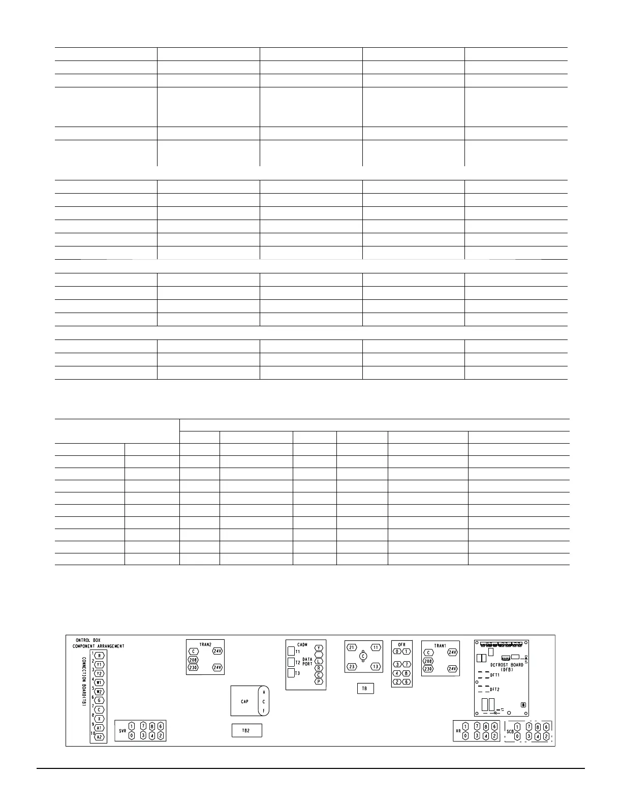
C11044
Fig. 24 -- Defrost Control Board (DFB) Location