32 506 01 2303 01
Specifications are subject to change without notice.
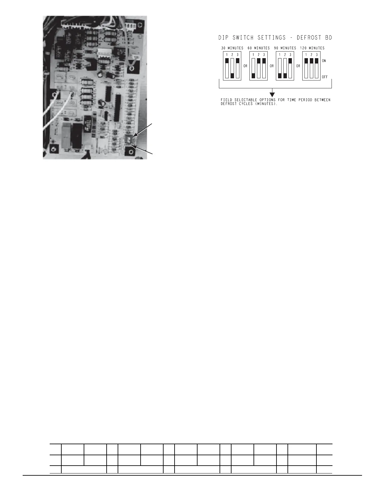
DIP
Switches
Speed-Up
Jumpers
C09275
Fig. 25 -- Defrost Control Board (DFB) Arrangement
Reversing Valve Control —
The DFB has an output for unit reversing valve control.
Operation of the reversing valve is based on internal logic;
this application does not use an “O” or “B” signal to
determine reversing valve position. Reversing valve is
energized dur ing the Cooling stage and de-energized during
Heating cycles. On ce ener g ized at the star t of a Cooling
stage, the reversin g valve will remain energized until the
next Heating cycle demand is received. Once de-energized
at the star t of a Heating cycle, the reversin g valves will
remain de-energized until th e next Cooling stage is initiated.
Compressor Control —
The DFB receives inputs indicating Stage 1 or 2 Cooling
and Stage 1 Heating from the space thermostat or unit
control system (PremierLink); it generates commands to
start compressor with or without reversing valve operation
to produce Stage 1 or 2 Cooling, or Stage 1 Heating.
Defrost —
The defrost control mode is a time/temperature sequence.
There are two time components: The continuous run
period and the test/defrost cycle period. The temperature
component is provided by the defrost thermostat (DFT1)
mounted on the outdoor coil.
The continuous run period is a fixed time period between the
end of the last defros t cycle (or start of the curren t Heating
cycle) during which no defros t will be permitted. This perio d
can be set at 30, 60, 90 or 120 minutes by changing the
positions of DIP switches SW1 and SW2 (see Fig. 26 and
Table 10). The default run period is 60 minutes.
C10790
Fig. 26 -- DIP Switch Settings — Defrost Board
At the end of the continuous run period, the defrost control
will test for a need to defro s t. DFT1 controls the start and
termination of the defros t cycle. If DFT1 is still open, the
defrost test/run window is closed and the control repeats the
continuous run period. If DFT1 is closed, the defrost cycle is
initiated. The defro s t period will end when DF T1 opens
(indicating the outdoor coil has been cleared of frost and ice)
or a 10 minute elapsed period expires, whichever comes
first.
At the end of the unit defrost cycle , the uni t will be
returned to Heati ng cycle for a full continuous run period.
If the space heating load is satisfied and compressor
operation is terminated, the defrost control will remember
where the run period was interrupted. On restart in
Heating, the defrost control will resume unit operation at
the point in the run period where it was last operating.
Defrost Thermostat —
The DFT is a temperature switch that monitors the surface
temperature of the outdoor coil circuits. The switch is
mounted on a vapor header tube above the vapor header’s
center check valve. See Fig. 27 for specific unit size
locations.
During the Heating mode, this tube location contains cold
evapora ting fluid entering the outdoor coil’s evaporator
circuit; during Defrost/Cooling mode, this tube location
conta ins condensed liquid or mixed--phase condensing
refrigerant entering t he subcooler circuit. A surface
temperature below 30_F during Heating mode indicate s
the potential to form frost or ic e on the outdoor coil; this
condition will initiate a Defrost cycle at the next DFB test
period. During the Defrost mode , this tube location wil l
warm as the frost and ice on the outdoor coil are removed,
until the switch opens and terminates the Defrost cycle.
The DFT switch closes on temperature drop at 30_F(--1_C)
and resets op en on temperature rise at 8 0_F(27_C).
Table 10 – Dip Switch Position
Switch No.
12 12 12 12 3
1
J 1
J
1 1
J J
1 On
0
J
0
J
0
J J
0 0
J
Off
30 minutes 60 minutes 90 minutes 120 minutes Fan Delay