Do you have a question about the Bryston 9BSST and is the answer not in the manual?
Ensure adequate airflow across heat sinks for proper cooling; avoid obstructions.
Use quality wire, keep runs short, and use 12 gauge for runs over 3 meters.
Verify local voltage compatibility; use dedicated circuits for high loads.
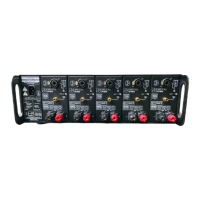
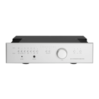
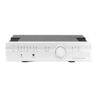
Allows switching between balanced and single-ended inputs for each channel.
Accepts XLR or 1/4" TRS; use quality shielded cables.
Accepts RCA or Phono connectors; use quality shielded cables.
Explains noise protection, cable length, and impedance differences.
Option to invert input signal polarity by 180 degrees for specific applications.
Adjustable gain (1V, 2V, 4V) for optimal matching with pre-amp output levels.
Connect loudspeakers to RED (+) and BLACK (signal ground) terminals.
Quick disconnect option; ensure post nut is tight for full insertion.
Provides high contact area and secure fastening; specific lug dimensions provided.
Insert wire up to 3 gauge through hole; secure with post knob.
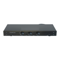
Touch-sensitive switch for applying/removing AC power to the amplifier.
Indicates channel status: unlit (no power), red (mute), green (normal), flashing red (clipping), orange (thermal shutdown).
Channels turn red (mute) during power-up, then green when supplies stabilize.
Indicates no AC mains power; may suggest blown channel fuses.
Flashing red light indicates output distortion due to overdrive.
Orange light signifies internal protection activating due to overheating.
Protects the amplifier; should be ON during operation, OFF for installation.
Connects the power cord; verify local voltage rating at connector.
Selects local (front switch/external control) or auto (switched outlet) power-up.
Uses 4-12V AC/DC voltage for remote power-up/down via 'IN' terminals.
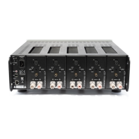
Details screw removal for channel access; advises caution with channel handling.
Illustrates typical wiring for a 5.1 system using the amplifier with a processor.
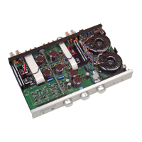
Visual representation of the amplifier's internal signal path and components.
Shows noise levels across frequency range, with balanced input details.
Displays harmonic content across frequency, noting even-order dominance.
Illustrates frequency response with different loads and power levels.
Shows phase shift across frequency for different loads and power levels.
Presents distortion levels across frequency, unaffected by load.
Shows intermodulation distortion levels across frequency for different loads.
Illustrates damping factor across frequency with an 8-ohm reference.
Shows channel-to-channel crosstalk with different driven loads.
Explains wiring and sensitivity settings for bridging two channels.
Discusses increased heat and potential thermal shutdown during bridged operation.
Details available Y-adaptor and ground strap cables for bridging.
Provides detailed diagrams showing overall unit dimensions in inches.
Details power output per channel into 8 and 4 ohm loads.
Lists dB gain and corresponding input voltage for 120W output.
Specifies impedance for single-ended and balanced inputs.
Quantifies total harmonic distortion plus noise for specified loads.
Provides noise levels relative to rated output for different gain settings.
States the slew rate in volts per microsecond.
Defines the frequency range for amplifier operation.
Specifies the damping factor at 20 Hz reference.
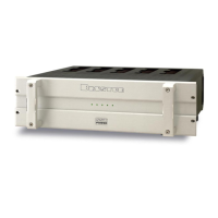
Lists unit dimensions for rack mounting and standard versions.
States the total weight of the amplifier.
Details power draw and heat dissipation for various operating conditions.
Provides essential safety warnings regarding electrical shock, ventilation, and operation.
Outlines warranty period, coverage, transferability, and service procedures.
| Gain | 29 dB |
|---|---|
| Frequency Response | 20 Hz - 20 kHz |
| Damping Factor | >500 |
| Dimensions | 19" |
| Input Impedance | 20k ohms |