aligndcnt
in the frame.
Adjustment
is
prcferably
carried
out with
the
aid of a shaight
edge
placed
ålong the
sides
of the
wheels,
In the case
of machines
fitted with tyres
of
thJ same
size on
fiont and rear
wheels,
the straight
edge
should touch
both
sides ofboth
tyres.
Ifthe front tyre is;f
a smaller
section
than the rear,
due allowance
will
have to
be made
for this.
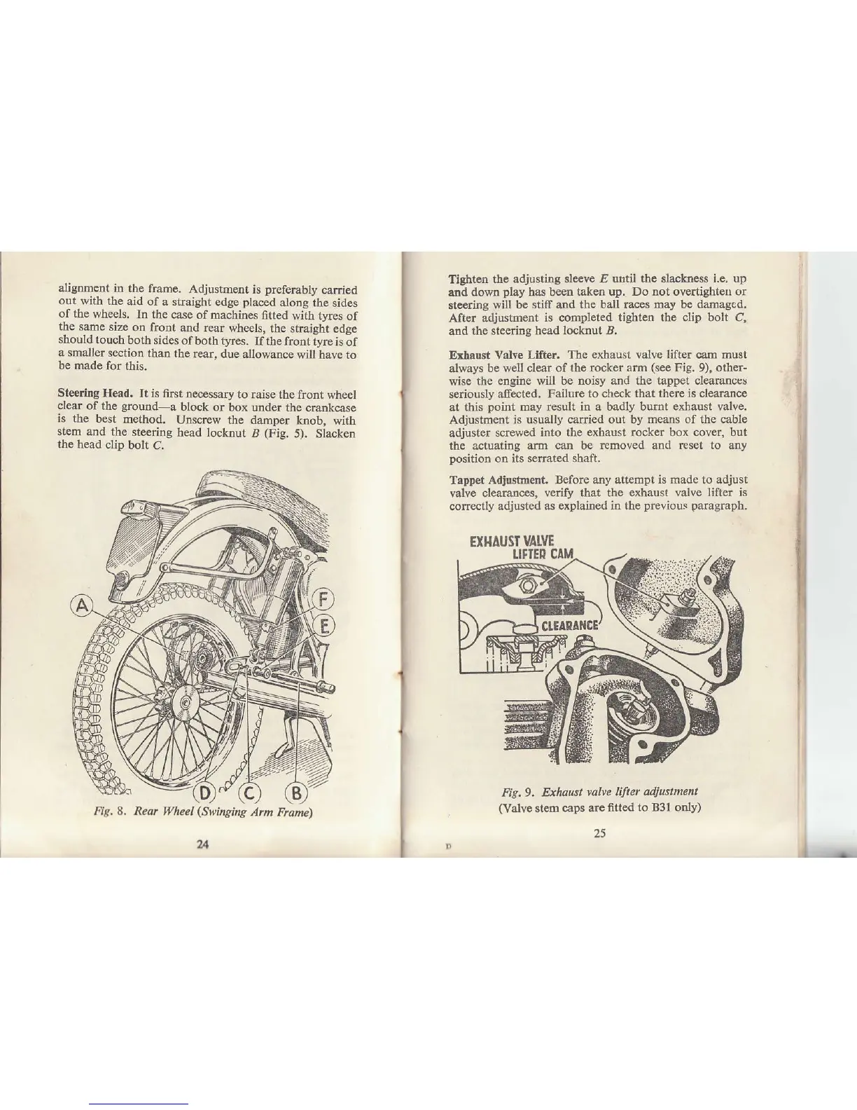
Steering Head.
It is first necessary
to
raise the frcnt
wheel
clear
of the
ground-a
block or
box under the crarkcase
is the best
method.
Unsøew
the damDer
knob- with
stem
and the
steering
head locknut
B
(Fig.
5). Siacken
the
head clip
bolt
C.
Fiq.8. Reor Wheel
(Swihging
Am Frane)
u
I
--r-
Tlghten
tie adjusting
sleeve E until the slackness i.e, up
atrd
down
play
has been
taken up. Do not overtighteo or
stcering will
be stiff and the ball {aces may be
damaged.
After adjushnent
is completed tighten the clip bolt C,
atrd the
steedog head locknut B.
Exhaust Valre
Llfter.
The exhaust valve lifter oam must
always
be well clear of
the rocker arm
(see
Fig.
9),
other-
wise
the engine will be
noisy and the tappet clearanccs
seriously affected, Failure
to check that there is cleamnce
at this
point
may result in a badly bumt exlaust valve.
Adjustment
is usually caried out by
means of the cable
adjuster
sdewed into the
exhaust rocker box cover, but
the actuating
arm can be
r€moved and ftset to arny
position
on its serated
shaft,
Tappet
Adiustment. Beforc any attempt
is made to adjust
valve
clearances, verify that the
exhaust valve lifter is
corle4tly
adjusted as
explained in the
previous pangmph.
EII.IAUST
VÅIVE
Fig.g. fuhaust
rølve lifter
adjustment
(Valve
stem cåp$
are fftted
to B31 only)
I
I
I
l