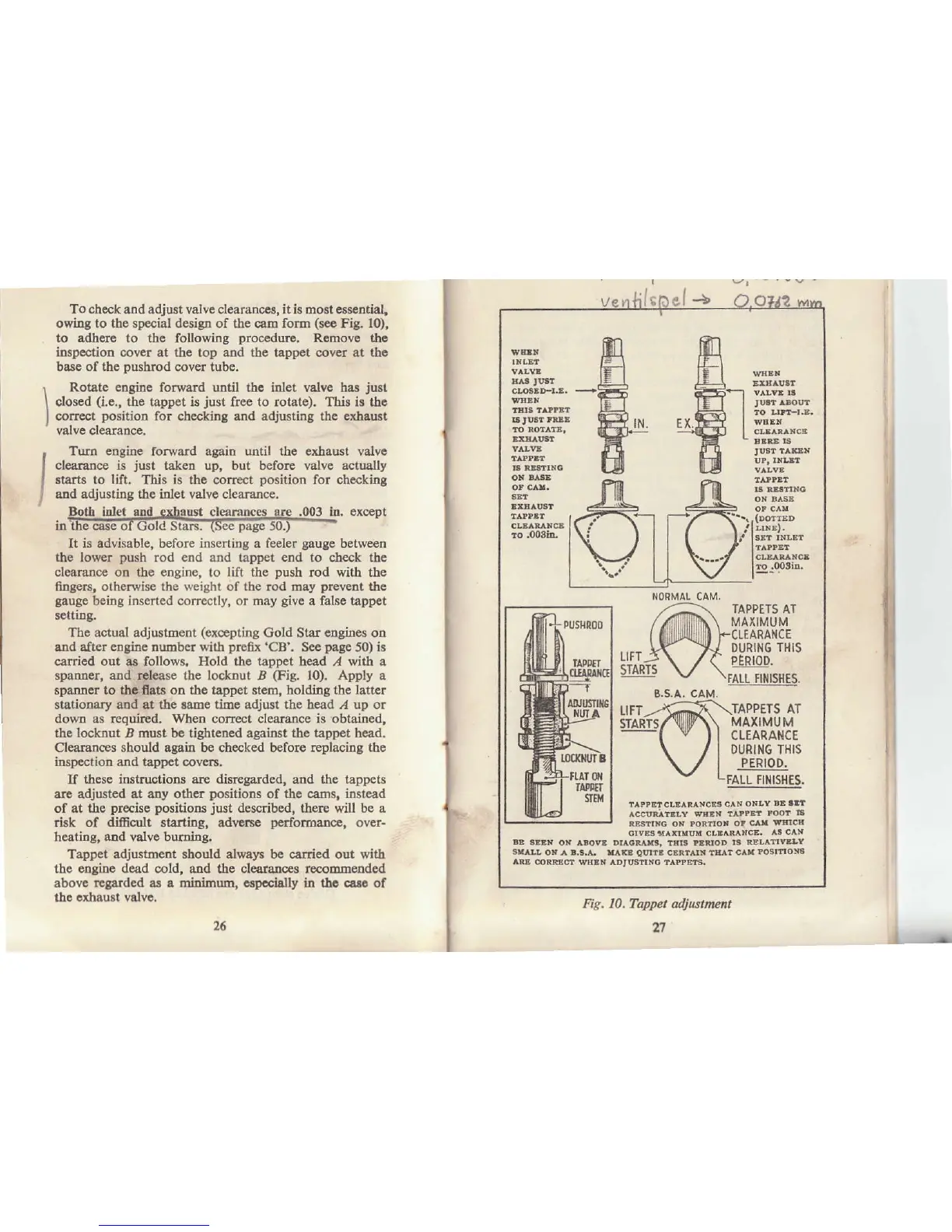
To check
and adjust valve clearanoes, it i!
host eslential,
owing to the
special
design of the cam form
(sc€
Fig. lO),
to adhcle to the
following
procedure.
Romove thc
inspection cover at the top and the tappet cover .t tho
base of the
pushrod
cover tubo.
I
Rotate enginc
forward until rbc idet vslve bas
just
I
closed
(i.e.,
tbe tappet
is
just
frec
to
rotate). Thir is tha
I
corrcct
position
for
che.kiDg and adjusting
thc exhrurt
'
valve clearance.
I
Tum cngine forward agBin until the exhausl valve
I
clearance is
just
tak€n
up, but beforc
valve actuslly
I
slarts to lift.
This
is tbe
cor.ect
positjon
for checkinS
J
and adjusting the inlet valvc clearance.
'
Both htet and exhaust cleamnces
are
,003 ltr. exceDt
ln the
cåse oI
(iotc
5tius.
(tee
page
Ju.,
It is advisable, b€fore inscrtirg a feeler
gaugo
between
the lower
push
rod €nd and tappet end to ch€ck thc
clearance
on the
ongine,
to
lift the
push
rod with the
fngers,
otheipise
the weight of the rod may
prevent
thc
gauge
being inserted corectly, or may
give
a falso tåppet
sctuDg.
Thc actual adjultment
(excepting
Gold Star
cngiDes
otr
atrd afte! engine truDbcr with
prefii
'CB'. S€€
page
50)
is
carriod out a8
follows.
Hold the tappet head ,4 with a
spantrer, and rclease the locknut B
(Fig.
1O). Apply a
spatrocr to tha ats oo the trppet stem, holdiog the
latt€.
statioDary aDd at the lamc ti[re adjust the head I up or
dowD as requfuid. When correct clearance is obtained,
the locknut
,
must be tighteDed against the tappet heåd.
Clearances
should agaitr be checked before replacing the
inspeatioo and tlpp€t cavers.
If
thcse instrugtions are disregarded,
and
the tappets
are adjusted
at
aDy
other
positions
of the ca$s, insteåd
of at tle
precise positions
just
described, there will be a
rfuk of dificlrlt startiag, adrc$e
perfomatrce,
ov€.-
heating, and valv€ buming.
Tappet adjustment should always b€ cå.ried out with
thc eagine dead cold, sud the clearances r€coomended
above
rgarded
a! a
miniqum,
ospacis[y h tho oaro of
thc
cxhaust valvc.
I
ro .008iD"
FALL FINISHES.
^ccvnrltl,?
BE
r^ia
om.E
cERtar!
tE^t
clf
rosrtlox!
^E
coRFlct wHrN rDtus
B.S.^. CAM.
l
Fig. 10. Tappet adjustmen
a1