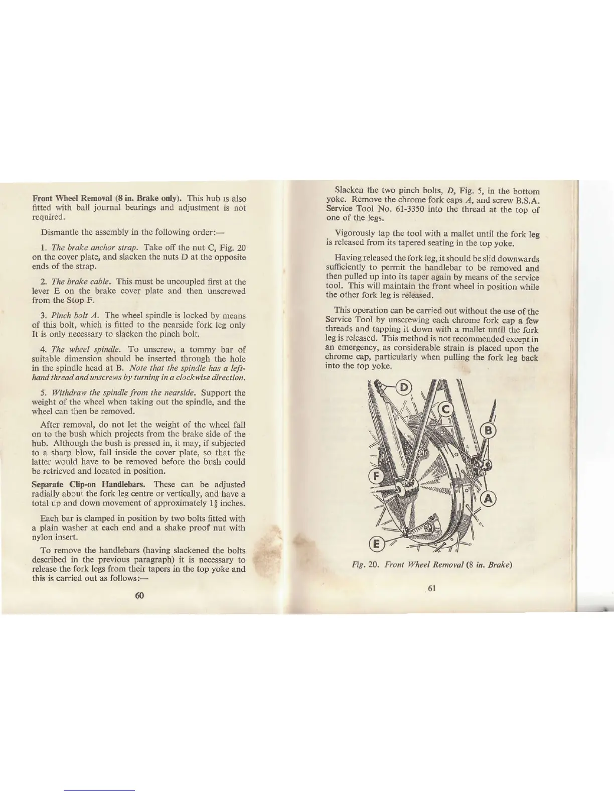
Frodt Wheel
Remorol
(t
in, Brake only).
This hub
ls also
fitted with baf
journa]
bearings
atrd adjustment
is not
requircd.
Dismantle
the
assembly
in the following
order:-
1. The btuke anchor strøp. Take off the nut
C, Fig. 20
on
the cover
plate,
and slacken the outs D at the
opposite
€nds
of the stap,
2.
The brake cable. This must be uncoupled
fiIst at the
lever
E on the brake cover
plate
and then
unsøewed
from the Stop F.
3.
Pinch bolt A. The wheel spindle is locked
by means
of
this bolt, which is fitted to the nearside fork
leg only
It
is only nec€ssary to slacken the
pinch
bolt.
4.
The wheel spindle, To unscrew,
a
tommy
bar of
suitable
dimensiotr should be inserted through
the hole
in the spindle
head at B. Nole tfutt rhe spindle
has a left-
hand
thrcad and unscrews
by
twning in a clockwise
dircction,
5. Withdruw
the spindle
from
lhe nearside.
Support the
weight of
the wheel when takiig out tåe
spitrdle, aDd the
wheel
can then be rcmoved.
After
removal, do not let the weight of the wheel
fall
on
to the bush which
projects
from the brake side
of the
hub.
Although the bush is
pressed
in, it may, if
subjected
to
a
sharp
blow, fall inside the cover
plate,
so that
the
latter would have
to
be
removed before
the bush could
be ietrieved and
located in
position.
Separate Clip-on
Hrflllebars, These
can be adjusted
radially about the
fork leg centre or vertically,
and have
a
total up and down
movement of approximately
1* hches.
Each bar is clamped
itr
position
by two bolts fitted
with
a
plain
washer at each end aDd a shake
proof
nut
with
Dylon insert.
To remov€
the handlebars
(having
slackened
the bolts
describ€d
in the
previous paragraph)
it
is
Decessary
to
release
the fork legs from their tapers in
the top
yoke
atrd
this
is carried out as follows:-
Slacken the
two
pinch
bolts, D, Fig.
5, in the
bottom
yoke.
Remove
the chrome
fork caps ,{,
and screw
B.S.A.
Service Tool
No, 6l-3350 into
the thread
at
the toD
of
on€
of the legs.
Vigorously
tap the tool with
a mallet until
the fork
leg
is rel€ased
from its
tapercd seating
in the top
yoke.
Having released
the fork leg,
it should
be slid downwatds
sufficiently
to
pemit
the
haDdlebar to
be removed
and
then
pulled
up
into its taper
again by means
of the
service
tool, This will
maintain the
front wheel in
Dosition while
the
other fork leg is
released.
This operation
can be carried
out without the
use
of the
Service
Tool by unscrewing
each
chrome fork
cap
a few
threads
and tapping it
down
with a mallet until
the
fork
leg is relealed,
This method
is not
rccotnrnended
exceDt
in
an emerg€ncy,
as coDsiderable
strain is
placed
upon
the
chrome
cap,
particularly
when
pulling
the fork
leg back
into the rop
yoke.
il
i
t,
i
:
Fig, m.
Front llheel
Removal
(8
in. Bruke)
6
6l