Connect
up the oil feed and
rctum
pipes
to
the rocke.s
and inlet rocker box, Replace
engine steadying
stay.
Replace
the rocker box covers, the carburetter,
the
exhaust
pipe
and silencer,
and fnally, the
petrol
tank
and
petrol pipe.
It
is advisable to remove the sparking
plug
aDd clean
it
beforc
replacing.
(see page
34.) Check
that the
gap
between
the
points
is conect and adjust
, ,
iI Decessary,
/tqh["
d#få,n.
p!{fqY.
u,.,.-ou.o ror aoy
reason
nore rhat th"e
engine'l$lift
pinion
and cam
pinions
are
marked to faoilitate assembly.
As the cams are
inter-
changeable
the timing marks are
duplicated on both
pinions.
The 'dash' mark only
is
used for
the inlet cam
and
the 'dot'for the cxhaust
cam
(see
Fig. l7). These
instructions apply equally to Competition
engines.
_
{For Cold
Stars fitted
with
specjal cams
sce
page
52.)
Aat.a
hDFhAuq'|t^q
Rear Sdspensibn
(Plunger
type), To
dismantle the rear
suspension,
first detach the rear wheel.
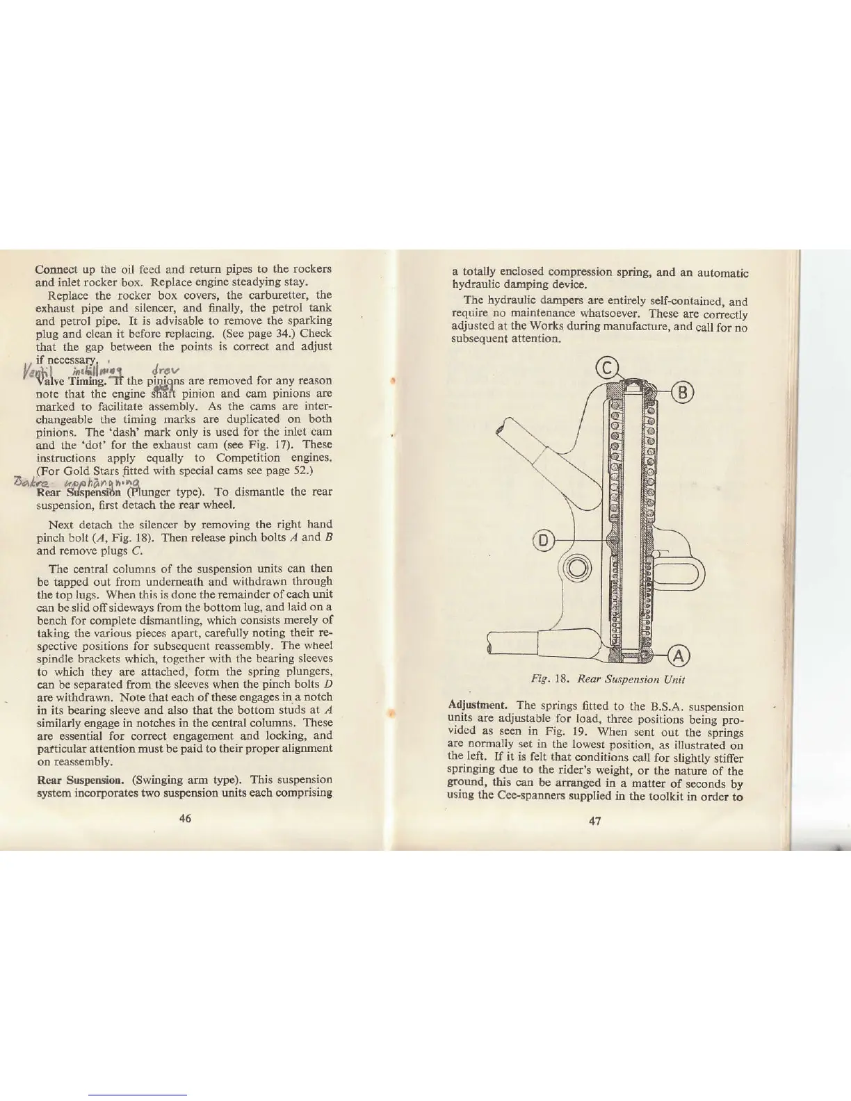
Next detach the silencer by removing
the right
hand
pinch
bolt
(.4,
Fig. 18). Then
rclease
pinch
bolts .4
and B
and remove
plugs
C.
The central
columns of the suspension
units can theD
be tapped
out from undemeath and withdøwn
through
the
top lugs. When this is done the remainder
of each unit
can beslid offsideways from the bottom
lug, and
laid
on
a
bench
for complete dlsmantling,
rvhich consists merely
of
taking the
vadous
pieces
apart, caxefully noting
thek rc-
spective
positions
for subsequent reassembly,
The wheel
spindle bruckets
which, together with the bearing
sleeves
to
which they aæ attached, form the spring
plungers,
can be
separated fiom the sleeves when
th€
pinch
bolts D
arc
withdlawn. Note that each of these
engages in a notch
in its bea.ridg sleeve and also that the botlom
studs at .4
simila.rly etrgage in notches in the central
columns. These
are essential for corect engagement and
locking, and
pafticular
attention must
be
paid
to their
proper
aliSnment
on r€assembly.
Reår Suspension.
(Swinging
alm type).
This suspension
system incorporates two suspension units
each cornprising
a
totally
etrclosed
compression
spriog,
4nd atr automatic
hydraulic damping
device.
The hydraulic
dampe$
are entirely
self-contained,
and
require no maintenance
whatsoever.
These aæ
conectly
sdjusted
at
the Works
dufing manufactute,
alld
call for no
subsequent attentioo.
Fig. 18.
Rear Suspensiott
Unil
Adjustment.
The
springs fifted
to the
B.S.A. suspeosion
units
are adjuslable
for load, rhree
positioos
being
pro-
vrdecl
as
seen in Fig.
19. When \ent
out tbe springs
are normally
set irl the lowest
position,
as illustrated
on
the
left.
If it is
felt that
conditions
call for slishtlv
stifer
springing
due to
the rider's weighr,
or the naiurj
of tle
ground,
this can
be arranged
in a mattet
of seconds
by
using
the
Cee-spanneN
supplied
in
the toolkit in
order to
46
41