r
I
grease
during assembly and wll last until the
machine is
in need of a complete overhaul.
MAGNETO.
Cleanlng
and Adiushnent. About
every 3,m0 miles
lemove the contact breaker covet and
examine the
contact breaker. If the contacts are burned
or blackened.
clean them with 6ne carborundum
stone or fine emery
cloth and afterwards
wipe away dust or dirt with a
petrol
moistened cloth. Check
the
contact
breaker setting afler
cleaning.
To check the coDtact
breaker setting, tum the
etrgine
until the contacts
are fully opened and
insert the
gauge
provided
on the ignition
spanner. If the setting is corect
(.012
to .015 in.) the
eauge
should be a sliding fit. Ii how-
ever, the
gap
vades appreciably
from the
gauge,
slackeD
the locknut on the
fixed contact and tum the contact
screw until the
gap
is set to the
gauge.
Final,J tiSbteD
the
locknut.
Next
examine the
pick-up,
which can
be rcdoved
when the fixing screws zue withdmwn, See
that the
pick-up
brush moves freely
and while it is removed,
clean the slip ring
track and flanges with a soft dry
cloth.
Lubrication
(every
3,000 miles). The face
is lubri-
cated
from
a
wick contained in the contact
brcaker base.
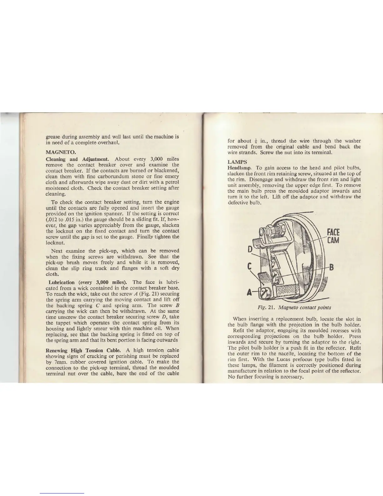
To reach the wick, take out the søew
,4
(Fig.
21) securing
the sp ng arm carrying the
moving contact and lift ofr
the
backing
spiing C
and spring arm. The screw B
carrying the
wick can then be rrithdrawn.
At the
same
time unscrew
the contact breaker seculing
screw D, take
the lappet
which operates the contact
sping fiom its
housing and
lightly smear with thin
machine oil. When
replacing, see
that the backing spring
is fitted on top of
the
spring alm
and that its bent
portion
is facing outwards
Renewing High
Tension Cabl€. A
high tension cable
showing signs
of cracking or
perishing
must be rcplaced
by
7mm. rubber covered
ignition cable. To
make the
connection
to the
pick-up
terminal, thread the
moulded
terminal nut over
the cable. bare the
end
of
the
cable
,
for
about
*
in., thread the wire
tbrough the washer
r€moved
from the original cable and
bend
back
the
whe strands. Screw the nut into
its
termiDal.
LAMPS
Heådlåmp.
To
gain
access to the bead
and
pilot
bulbs,
slacken the
front rim retaining screw,
situated at the top of
the rim. Disengage
and withdraw
the front rim and light
uni! assembly, removing
the
upper edge firsl. To remove
the main bulb
press
the
moulded
adaplor inwards and
turn it lo the letr. Lift off the adaptor and rithdraw the
defective bulb.
When inserting a replacement bulb, Iocate the
6lot
in
rhe bulb llange with the
projection
in the bulb
holder.
Refit the adaptor, engaging its moulded recesses wirh
corresponding
proje.tions
on the bulb holder.
Press
inwards and secure by turning the adaptor to the n'ght.
The
pilot
buib holder
is
a
push
fit
in
the reflector, Refit
thc outer
rim to
the
nacelle, Iocating
the bottom of the
rim 6rst. With the Lucas
prefocus
type
bulbs fitted
in
these lamps, the filament is coffectly
positioned
during
manufacture in relation to the focål
poinl
of
the reflector.
No further focusing is necessary.
Fig,2l, Magneto contact
points