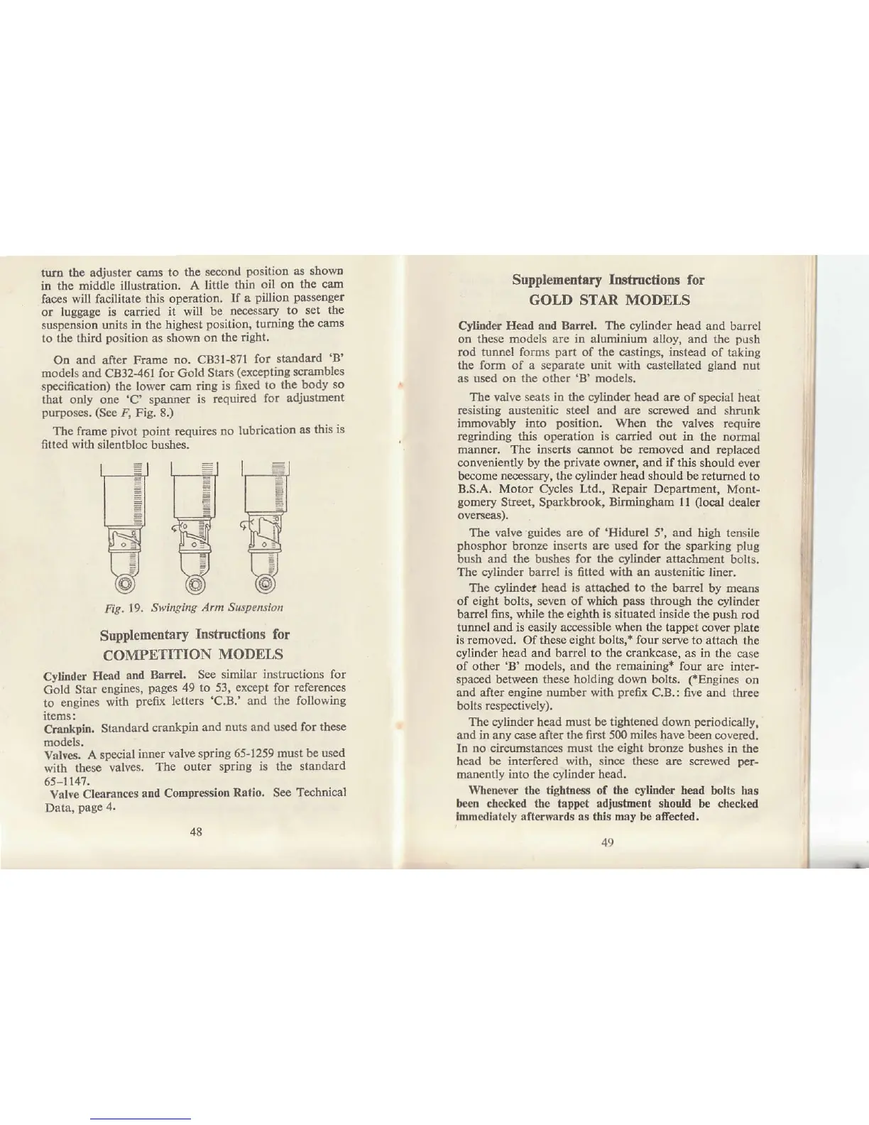
tut'n the adjust€r cams
to tho
second
positioD
as
sholrD
in the middle
illusb'ation. A
little thin
oil oD
the cam
faces will facilitat€
this operation,
lf a
pillion passengel
or
luggage is carried
it will be
necessary
to set
the
suspension units in the highest
position,
tuming
tho cams
to the third
position
as shown
on the
right'
On and after Frame
no. CB3t-871
for
standard
'B'
models and CB32-461 for
Gold Stars
(exceptiDg
scranbles
specificåtion) the
lower cast ring
is fir(€d
to the
body
so
that only
one
'C' spaffrer is
rcquited
fo!
adjustmcnt
purposes. (See
4
Fig.
8.)
The
frame
pivot point
rcquircs
no
lubrication
as
this
is
fitted
with
silentbloc bushes.
Fig.19.
Swinging
Arm SusPension
Supplementary
Instructions
for
COMPETITION
MODELS
Cytfuder
Heåd
and
BåIrel,
See similar
instructions for
cold Star
engines,
pages
49 to 53,
€xcept
for
references
to
engines
with
preflK
letters
'C'B.'
atld
the following
llems;
Cra
pin.
Standard
craDkpin
and
nuts
and
used for these
models.
Valves.
A
special
inner
valve spdog 65-1259 must
be used
with
these
valves,
The outei
spring is the standard
65-1141.
valre
Cl€arances
and ComDr€ssion
Ratio. See
Technical
Data,
page 4.
Supplementary Inshuctions for
GOLD STAR
MODELS
Cylinder
Heåd ånd Bftrel. The cylinder head
and barrel
on
these models
are
in
aluminium
alloy,
and the
push
rod tunnel forms
part
of
the cåstings, instead
of taking
the form of a separate unit with castellated
gland
nut
as used on the other 'B' models.
The valve seals in the cyliDder head are of special
heat
resisting austeoitic ste€l and aae screwed and shmnk
imrbovably into
position.
Whetr the
valves require
regrinding this
operation
is carried out in
the normal
ftanner. The inserts cannot
be
removed
and replaced
conveniendy by the
private
owner, and if this
should ever
become necessary, the cylinder head shouid be rctumed
to
B.S.A. Motor Cycles Ltd., Repair Department,
Mont-
gomery
Street, Sparkbrook, BirminSham 1l
(local
dealer
oveEeas).
Tbe valve
guides
are of
'Hiduel
5', aod high t€nsile
phosphor
b.oDze
ioserts
are
used
for
the
sparking
plug
bush and the bushes for
the cylinder
attachment
bolts,
The
cylinder
barrel
is
6tied
with an austenitic
liner.
The
cylindel
head
is
attached
to the
barrel by means
of
eight
bolts, seven
of which
pass
through
the cylinder
barel
fins, while the eighth is situated inside the
push
rod
tunnel
ard
is easily
accessible
when the tåppet
cover
plate
is
removed.
Of these
eight
bolts,r
four serve
to attach
th€
cylinder head and barrel to the crankcase, as in
the case
of other
'B'
models, and the remaining* four are
inter-
spaced between these holding
dou,l
bolts.
(*Engines
on
and after engine number with
prefx
C.B.: five and
thrce
bolts rcspectively).
Th€ cyLinder hcad must be
tiShtened do*n
periodicålly,
and irl any case after
the
first 500
miles have
been coveæd.
In
no
circumstances
must the eight bronze
bushes in the
head be intedered with, sincæ these are screwed
!'cr-
manently itrto the cylinder head.
Wheneyer
the
tightne$! of the cylifiler
head bolts has
lre€n checked the tåppet adiushnent should
be checked
Immcdis(cly afterwards as this may be afect€d.
48
49