Design and Function
3
ekr 500 digital Unit Touch – Application with Wide Array Edge Sensors 9/39
3 Design and Function
3.1 Components
A standard web guiding system with wide array edge sensors com-
prises the following components:
■ One ekr 500 digital Unit Touch web guiding controller
■ One or two ultrasonic or infrared wide array edge sensors
including connection box
■ One guiding device (e.g. rotating frame guide)
■ One actuator (integrated in the guiding device)
■ One set of connecting cables
3.2 Design
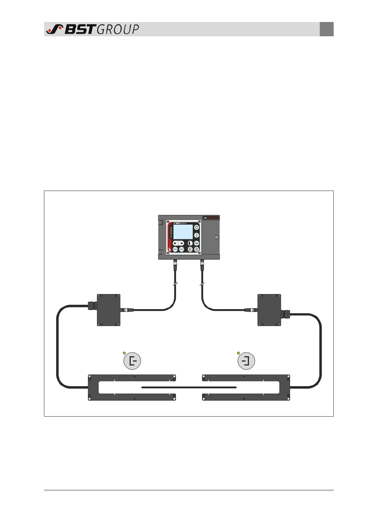
Controller
ekr 500 digital Unit Touch
Connection box
CAN bus CAN bus
Wide array edge sensor 1 Wide array edge sensor 2
Connection box
X102 X103
Fig.1: ekr 500 digital Unit Touch controller with wide array edge sensors
The wide array edge sensors are connected to the CAN bus inter-
face of the controller as Sensor1 or Sensor2 using a special con-
nection box. The connection box is part of the scope of delivery.
 Loading...


