Operational Description
POWERplus User Guide 1.1.0 13 350-00104-4
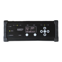
Battery Settings
The Battery Settings Page (Figure 9) shows the user settings relating to the battery connected to the
POWERplus system.
• Battery Type
o Choose the battery type corresponding to the battery connected to POWERplus. This
configures the charger to suit the specific battery.
• Charger Enable
o Set ENABLE if you have a battery connected and want to use the internal battery charger. It
is recommended to disable the charger if no battery is connected.
• Maximum Charge Current
o Choose the value suitable to charge the capacity of the battery (Ah) connected.
The actual charge current will be at or below this level depending upon the state of charge of
the battery. Consult with the battery manufacturer if you are not sure of the recommended
charge current.
• Auto Off
o Select ENABLE to allow POWERplus to disconnect the battery from the output when the
battery voltage falls below the VL Limit.
Selecting the OFF option will keep the battery connected to the output even when the
voltage falls below the VL limit.
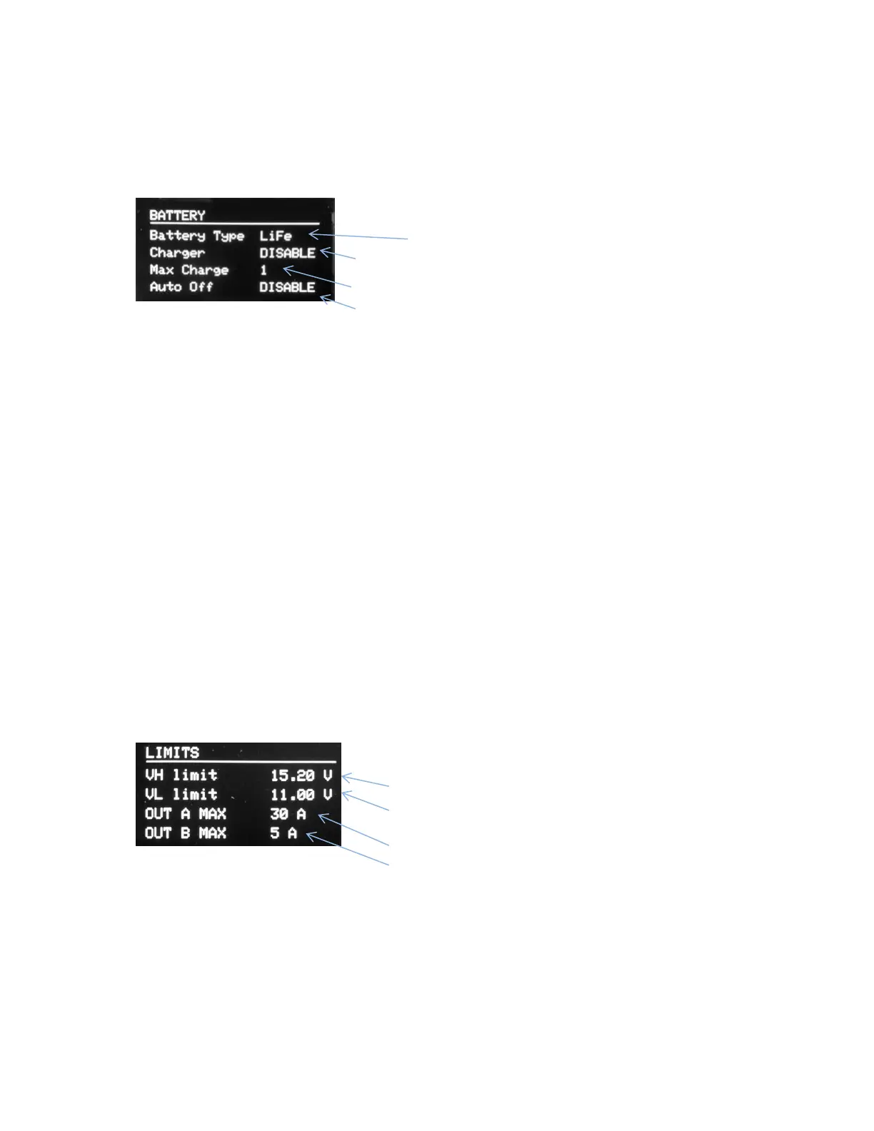
Limit Settings
The Limit Settings page (Figure 10) shows the user settings related to the upper and lower disconnect
voltages and the maximum output current settings.
• VH Limit
o Set the upper limit trip voltage to suit the maximum value your equipment is rated for. A
voltage higher than this threshold will cut off the voltage to the outputs. The output will
remain disconnected until the voltage has fallen at least 1 V lower than this setting.