Functional Description
POWERplus User Guide 1.1.0 6 350-00104-4
Input Selection
When the DC input voltage is in range, POWERplus automatically selects the DC input as the power source
to feed the outputs. If the DC input is out of range, then POWERplus will automatically switch to the
battery input.
If you want to use the battery (for example to test the battery under load), choose the Battery input
selection (BATT). This is a manual way to use the battery as the power source even when the DC input is
within the normal range.
When using POWERplus in a mobile application you can configure it to use an additional (auxiliary)
battery which will be used when the vehicle engine is not running. POWERplus will automatically select
the auxiliary battery when the engine is not running.
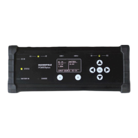
Input Status Indicator
The input status LED is located midway between the DC input and Battery input connectors on the left
side of the control panel. The LED glows GREEN when the DC input is selected and glows RED when the
Battery input is selected (see also Alarm Status Indicator).
Output Control
The two output groups (A and B) are individually protected by high efficiency output switches. The
outputs are independent and are automatically disconnected from the loads if the output current exceeds
the current set by the user for that output group.
The maximum total output current (A+B) is 40A. Output group A has priority over the maximum current.
For example, if you set group A to have a maximum output current of 35A, group B output cannot exceed
5A. See the AUTO OFF
o Select ENABLE to allow POWERplus to disconnect the battery from the output when the
battery voltage falls below the VL Limit.
Selecting the OFF option will keep the battery connected to the output even when the
voltage falls below the VL limit.
Limit Settings page for information on setting the output current limits.
If an output is disconnected because of excessive current the associated front panel group LED will be
extinguished. After clearing the fault, you can reset the output by pressing the appropriate A or B output
button. These buttons are alternate-action, so you can also use them to manually operate the output
switches.
Output Status Indicators
LED indicators are located midway between each of the two DC output groups. These LEDs glow green
when DC is applied to the associated group and extinguished when DC is disconnected to the output.
Alarm Status Indicator
The RED STATUS led will flash when the battery is connected, and the voltage falls close to the battery
cut-off threshold. If the beeper is enabled the audible alarm will also be sounded. The low voltage
disconnect threshold can be set in the AUTO OFF
o Select ENABLE to allow POWERplus to disconnect the battery from the output when the
battery voltage falls below the VL Limit.
Selecting the OFF option will keep the battery connected to the output even when the
voltage falls below the VL limit.