Installation1
Wall-mounted condensing gas boiler Buderus 800 - Subject to modifications resulting from technical improvements!
10
1.3.2 Air supply and flue gas exhaust in a closed
installation
To ensure optimal operation, the 800 Series appliances
must be connected to a Buderus wall-mounted or roof-
mounted flue terminal. These terminals have been
developed specifically for the 800 Series condensing
gas boilers and have been comprehensively tested. The
Buderus wall and roof-mounted flue terminal kits ensure
trouble-free operation.
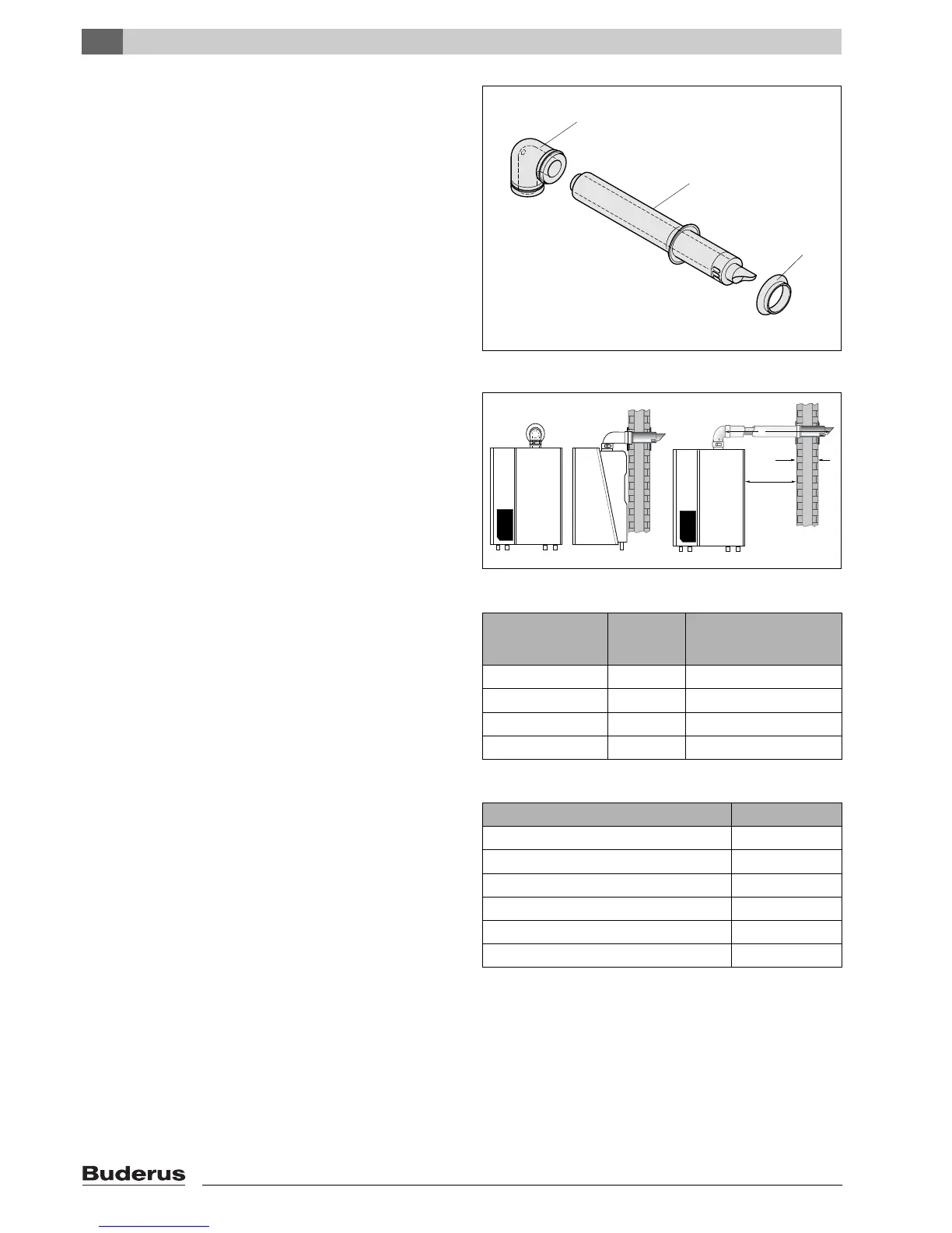
The following items for the flue (see fig. 2) are included
in the delivery of the boiler:
– pos. 1: 1 Concentric bend 80/125;
– pos. 2: 1 Horizontal flue terminal 80/125;
– pos. 3: 1 Flue finishing kit.
1.3.3 Maximum Flue length
The maximum pipe length of the air supply and flue gas
exhaust pipes for the 800 Series condensing gas boilers
(see table 2) is determined by the total pressure loss of
all components in the flue gas exhaust / air supply
system.
Maximum wall thickness without extensions is 550 mm.
Maintain a minimum side wall clearance of 50 mm (see
fig. 3).
1.3.4 Additional flue parts
Additional flue parts (see table 3) can be ordered from
your supplier.
fig. 2 Horizontal flue pack
Boiler
Maximum
pipe length
For every 90° bend the
maximum pipe length has
to be reduced by
800 – 24 / 24T25 H/V L = 14 m 0 m
800 – 29 / 29T25 H/V L = 14 m 0 m
800 – 43 L = 14 m 1.5 m
800 – 60 L = 9 m 1.5 m
table 2 Pipe length
Flue parts Order No.
Concentric pipe, 500 mm long, adjustable NE 83713
Concentric pipe, 1000 mm long, adjustable NE 83714
Concentric bend 90° NE 83715
Concentric bend 45° NE 83716
24-43 kW adaptor plate NE 79061
60 kW adaptor plate NE 79064
table 3 Additional flue parts