Installation 1
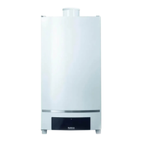
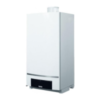
Wall-mounted condensing gas boiler Buderus 800 - Subject to modifications resulting from technical improvements!
9
1.3 Flue Installation
1.3.1 Siting the flue terminal
The flue must be installed in accordance with the
recommendations of BS. 5440-1:2000.
Pluming will occur at the terminal so terminal positions
where this could cause a nuisance should be avoided.
The air supply and the flue gas exhaust must meet the
applicable general regulations. Please consult the
instructions provided with the flue terminal kits prior to
installation.
The boiler MUST be installed so that the terminal is
exposed to external air.
It is important that the position of the terminal allows the
free passage of air at all times.
Minimum acceptable spacing from the terminal to
obstructions and ventilation openings are specified in
table 1.
If the terminal is fitted within 1000 mm of a plastic or
painted gutter or within 500 mm of painted eaves, an
aluminium shield of at least 1000 mm long should be
fitted to the underside of the gutter or painted surface.
If the lowest part of the terminal is less than 2 metres
above the level of the ground, balcony, flat roof or place
to which any person has access, the terminal must be
protected by a guard. Protective guards are available
from Quinnell Barrett and Quinnell, Old Kent Road,
London.
Ensure that the guard is fitted centrally.
The flue assembly shall be so placed or shielded as to
prevent ignition or damage to any part of the building.
The air inlet/products outlet duct and the terminal of the
boiler MUST NOT be closer than 25 mm (1'') to
combustible material. Detailed recommendations on the
protection of combustible material are given in BS.
5440- 1:2000.
If this could occur the appliance MUST be turned off
(with the owners permission), and labelled as unsafe
until corrective action can be taken.
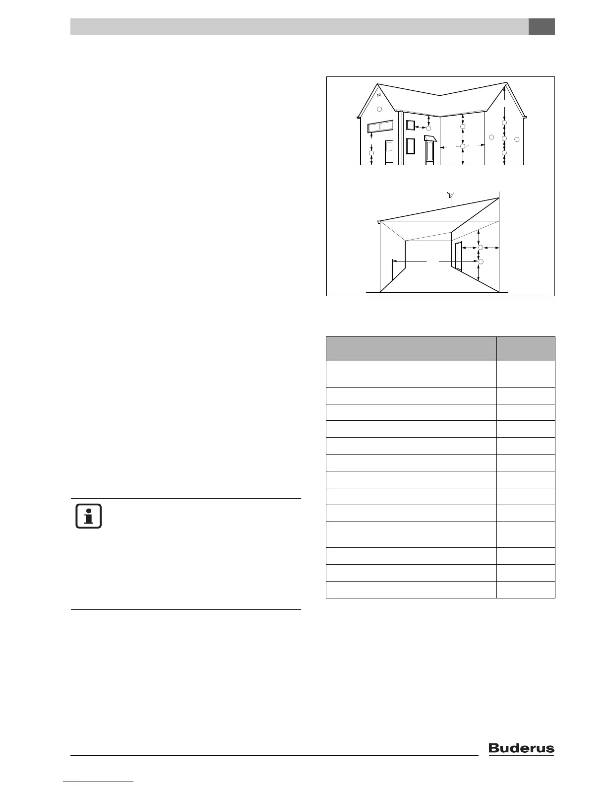
fig. 1 Flue terminal position
Terminal Position
Minimum
Spacing
A. Directly below or alongside an opening
window, air vent or other ventilation opening
300 mm (12")
B. Below guttering, drain pipes or soil pipes
75 mm (3")
C. Below eaves
200 mm (8")
D. Below balconies or a car port roof
200 mm (8")
E. From vertical drain pipes or soil pipes
150 mm (6")
F. From internal or external corners
300 mm (12")
G. Above adjacent ground, roof or balcony level
300 mm (12")
H. From a surface facing the terminal
600 mm (24")
I. From a terminal facing a terminal
1200 mm (48")
J. From an opening in a car port (e.g. door or
window) into dwelling
1200 mm (48")
K. Vertically from a terminal on the same wall
1500 mm (60")
L. Horizontally from a terminal on the wall
300 mm (12")
M. Adjacent to opening
300 mm (12")
table 1 Balanced flue terminal position
NOTE
It is absolutely essential to ensure, in
practice, that products of combustion
discharging from the terminal cannot re-
enter the building or any other adjacent
building through ventilators, windows,
doors, other sources of natural air
infiltration, or forced
ventilation/airconditioning.