Installation1
Wall-mounted condensing gas boiler Buderus 800 - Subject to modifications resulting from technical improvements!
6
1 Installation
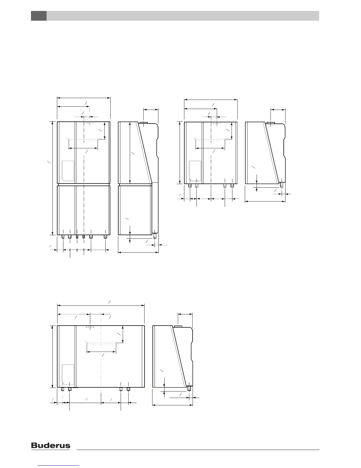
1.1 Dimensions, connections and
assembly
DHW warm out = hot water outlet 15 mm dia.
DHW cold in = cold water inlet 15 mm dia.
GAS = gas connection R½ (800 - 24/29/43)
and (800 - 24T25V/29T25V)
gas connection R¾ (800 - 60)
CH return = boiler return line 28 mm dia.
CH flow = boiler flow line 28 mm dia.
CWDO = condensate water drain 32 mm dia.