Installation1
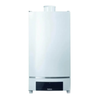
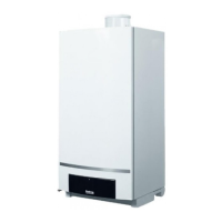
Wall-mounted condensing gas boiler Buderus 800 - Subject to modifications resulting from technical improvements!
14
On type 800 – 24T25 H/V and 800 – 29T25 H/V:
When using plastic pipes, note the information provided
by the pipe manufacturer. This particularly applies to the
mode of connection recommended by manufacturer.
In certain situations to prevent hammering within the
system when closing taps, controls can be installed
to counter act this action. For further information
please contact Buderus.
For the size of pipe connections please refer to the
wall mounting template.
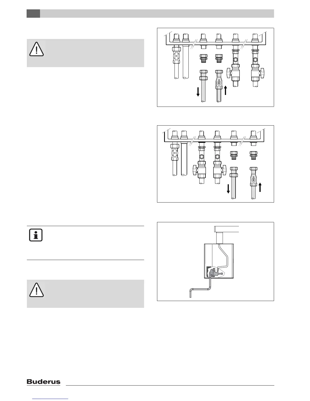
1.7.5 Condensate water drain
When shorter aluminium flue-gas systems are used
There is no integrated condensate water outlet in the
flue gas adapter of the aluminium exhaust flue.
The condensate water from the exhaust flue flows via
the gas boiler and into the boiler's odour trap (syphon,
see fig. 10).
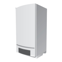
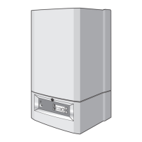
fig. 8 Hot water connection vertical boilers
(type 800 – 24T25V / 800 – 29T25V)
CAUTION!
Do not use galvanised pipes or fittings. The
hot water heat exchanger is made of copper
and risks electrolytic corrosion.
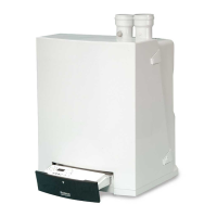
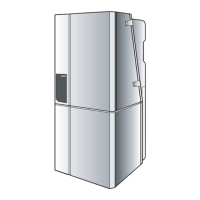
fig. 9 Hot water connection horizontal boilers
(type 800 – 24T25H / 800 – 29T25H)
fig. 10 Condensate water outlet for exhaust flue systems
made of aluminium
NOTE!
The condensate water collecting in the gas
boiler and possibly in the flue gas line must
be drained. Local regulations must also be
noted.
CAUTION!
If the flue gas adapter is made of aluminium,
the sealing cap (fig. 12, item 1) MUST NOT
be removed.