Installation 1
Wall-mounted condensing gas boiler Buderus 800 - Subject to modifications resulting from technical improvements!
17
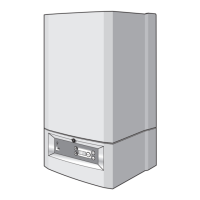
1.8.3 Flue duct preparation and assembly
Measure the flue length L. Refer to figure 16.
Mark of the lengths shown onto the ducts and cut the
length. The cuts must be square and free from burrs.
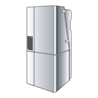
Terminal assembly outer (air) duct - L-70 mm, inner (flue)
duct - L-50 mm. The measurement is made from the ridge
at the terminal indicating the outer face of the wall.
Refer to figure 18.
Extension air duct - L-70 mm, flue duct - L-50 mm.
The measurement is from the formed end.
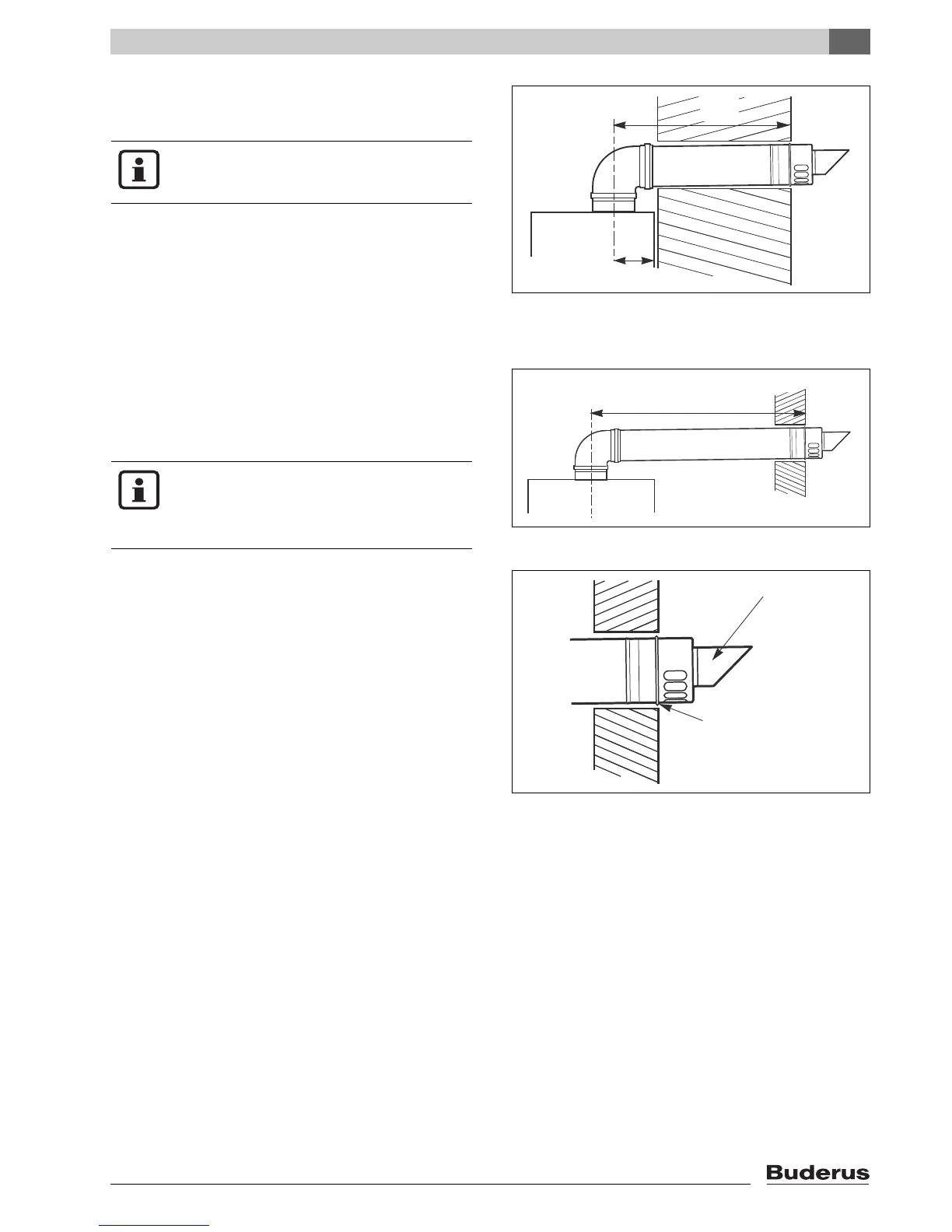
Assemble flue system completely. Push the ducts
fully together. The slope of the terminal outlet must
be face downwards.
The assembly will be made easier if a solvent free
grease is lightly applied to the male end of the ducts.
Push the assembly through the wall and slide the tur-
ret onto the flue connector. Refer to figure 14.
Ensure that the turret is fully entered into the socket
on the boiler. From the outside fix the flue finishing kit
to the terminal and, after ensuring the duct is properly
inclined towards the boiler, fix the finishing kit to the
wall.
If the terminal is within 2 m of the ground where there
is access then an approved terminal guard must be
fitted.
The guard must give a clearance of at least 50 mm
around the terminal and be fixed with corrosion re-
sistant screws.
fig. 16 Flue length - rear