Installation 1
Wall-mounted condensing gas boiler Buderus 800 - Subject to modifications resulting from technical improvements!
21
If the boiler has to be temporarily put into operation
without control unit, place a conducting bridge in
terminal 12 and set the feed temperature and the
required heating capacity on the UBA.
1.9.5 Buderus room temperature control device
connection
Remove the bridge in terminal 34 (fig. 22, item 2)
and connect the control unit to the terminal strap.
Remove the wire in terminal 12 (fig. 22, item 1).
1.9.6 230V room-temperature control device connection
Remove the cover of the RTH converter (fig. 22,
item 6).
Lead the control device wire through the cable lead
(fig. 22, item 8).
Fix the wire to terminal 1 and 2 of the 230 Volt con-
nection (fig. 22, item 9).
Secure the wire with the bracket and the two screws
onto the RTH converter.
1.9.7 Volt free external control device connection
Remove the cover of the RTH converter (fig. 22,
item 6).
Lead the control device wire through the cable lead.
Fix the wire to terminal 1 and 2 of the volt free con-
nection (fig. 22, item 10).
1.9.8 Service tool
The service tool allows you to determine the operating
status of the boiler, check components and carry out fast
fault
diagnosis.
Open the flap at the front of the boiler unit and insert
the twin plug connector of the service tool into the
sockets provided (fig. 23, item 1).
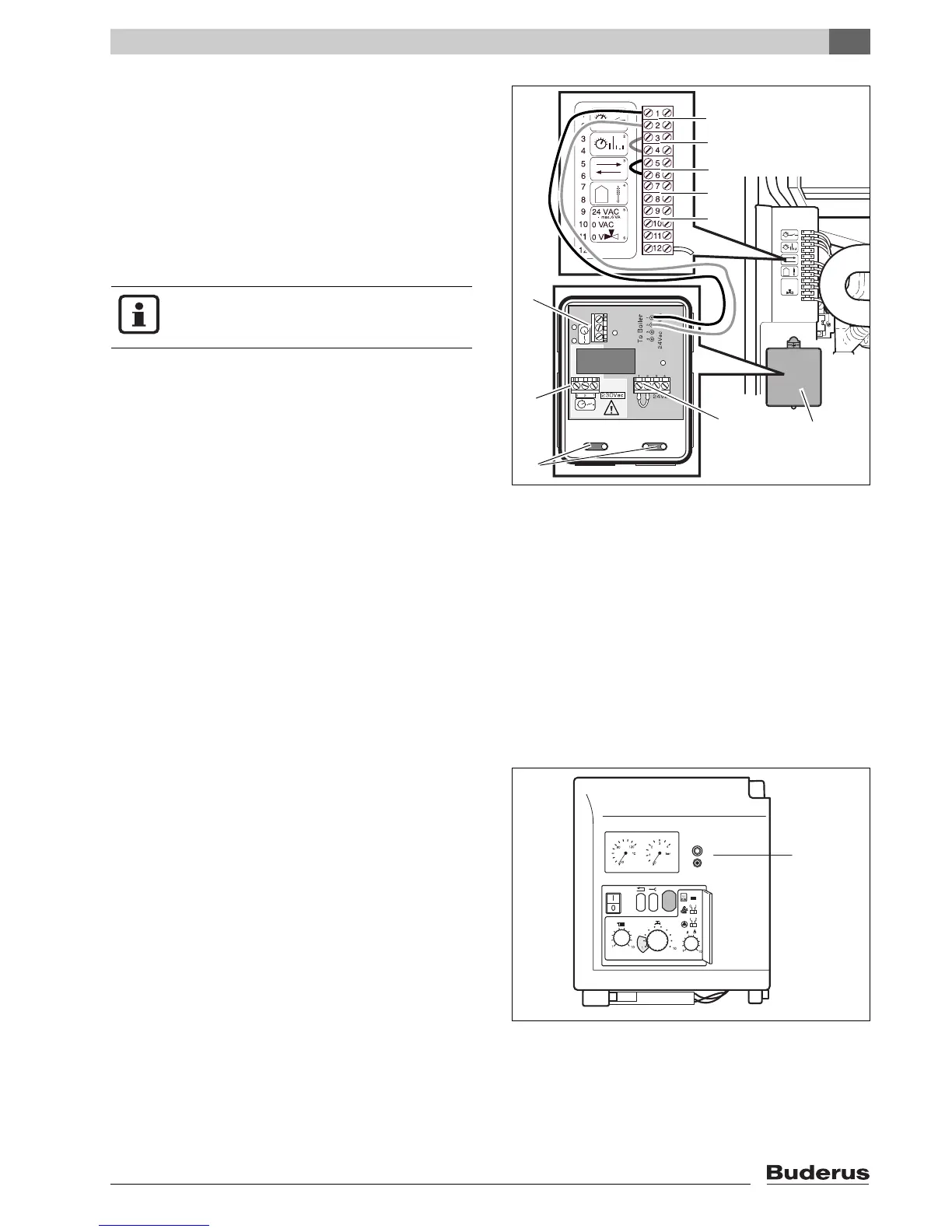
fig. 22 Connecting the control unit
Key to fig. 22:
item 1: ON/OFF temperature controller (non-conducting
bridge)
item 2: Room temperature controller iRT (digital)
item 3: I/O port/communication port
item 4: Outdoor temperature sensor
item 5: Power supply 24 VAC/max: 6 VA switching voltage
three-way valve (9+11)
item 6: RTH converter
item 7: 24 VAC connection
item 8: 230 VAC connection
item 9: Volt free connection