17
Replacing the packing gland
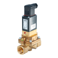
Type 2000, 2002, 2012
WARNING!
Risk of injury from ejected parts!
Whenthespindleopeningisexposed,theindividualpartsofthepackingglandarepressedoutatanunde-
nedspeedwhenthecontrolairconnectionispressurized.
▶ Beforepressurizingwithcontrolair,safeguardtheambientareaofthedischargeopening(e.g.place
spindleonarmbase).
→ Pressurize the lower control air connection with 6...8 bar.
→ Greasetheindividualpartsofthenewpackingglandwiththesuppliedlubricant(siliconegreaseOKS
1110-3).
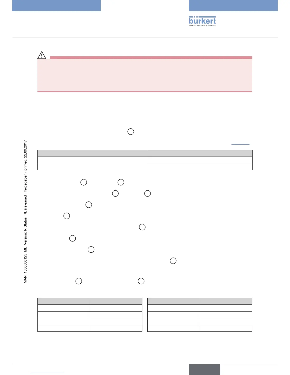
→ Placetheindividualpartsonthespindleintheprescribeddirectionandsequence.
→ Pushpackingglandpackingintothetube
8
.
→ Screwinspindleguideagainbeforeusingtheinstallationwrench.Observetighteningtorques(“Table2”)!
Spindle diameter (mm) Tightening torques (Nm)
10 6
14 15
Table 2: Spindle guide tightening torques
→ Place swivel plate
3
on the spindle
2
.
→ Aligndrillholesoftheswivelplate
3
and spindle
2
sothattheyareushwithoneanother.
→ Support swivel plate
3
on the cylindrical part with the help of a prism.
→ Insert pin
4
into the drill hole.
→ Calk pin bores on both sides of the swivel plate
3
with chisel or prick punch.
→ Clamp body
1
.
→ Replacegraphiteseal
5
.
→ Only for VA body (VA = stainless steel): Lubricate nipple thread
6
withKlüberpasteUH196-402.
→ ForcontrolfunctionAandI: Pressurize lower control air connection with compressed air (5 bar).
→ Screw in nipple
6
with actuator in valve body
1
.Observetighteningtorques.
Tighteningtorquesforscrewingthenippleintothevalvebody
DN (mm) Tightening torques (Nm) DN (mm) Tightening torques (Nm)
15 45 40 65
20 50 50 70
25 60 65 70
32 65
Table 3: Valve body tightening torques