24
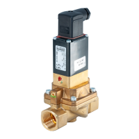
Conversion of control function
Type 2000, 2002, 2012
9.2 Conversion from control function A (CFA) to control
function B (CFB)
DANGER!
Danger – high pressure!
▶ Turnothepressureandventthelinesbeforelooseninglinesorvalves.
Risk of injury from improper maintenance!
▶ Maintenance may be performed by authorized technicians only!
▶ Toscrewonorunscrewvalvebodyoractuator,useanopen-endwrench,neverapipewrench.
▶ Observetighteningtorques.
Requiredparts:
Item Description
35 Pressurespring
30 O-ring
5 Graphiteseal
Procedure:
→ Mount valve
1
on the body.
→ Pressurize lower control air connection with compressed air (5 bar). Valve opens.
→ Screw actuator on the nipple
6
out of the valve body
1
.
→ Vent actuator.
CAUTION!
Danger through taut springs!
▶ Carefully open piston actuator!
→ Release cover
31
withspecialwrenchuntilthespringsarecompletelyrelaxed,holdinguptheactuator
body
12
againstthehexagon.
Forinformationaboutthespecialwrench,seeChapter“10Installationtools”.
→ ForactuatorsizeG,H: Remove washer
40
.
→ Removepressuresprings
28
29
.
→ Remove position indicator
26
with Allen key.
→ Carefully screw in actuator on the swivel plate
3
(only put pressure on the upper section of the swivel
plate).
→ Release nuts
25
.