8
5.2 Fluidic installation
Installation position: any, preferably actuator face up.
Flow direction (for normally closed/Safety Shuto Valves): The
letters on the valve body state the pressure (P) and outlet (A).
For normally open valves (not for Safety Shuto Valves): The letters
on the valve body state the pressure (P) and outlet (B).
→ Clean pipelines and ange connections.
→ Install dirt trap at the valve inlet (0.2...0.4mm).
Observe ow direction: from 1 (P) → 2(A) (WWA)
from 1(P) → 2(B) (WWB).
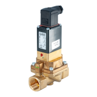
Valve with threaded connection:
→ Use PTFE tape as a seal material.
NOTE!
Caution! Risk of breakage!
▶ Do not use the coil as a lever arm.
→ Hold the valve using a corresponding open-end wrench and
screw into the pipeline.
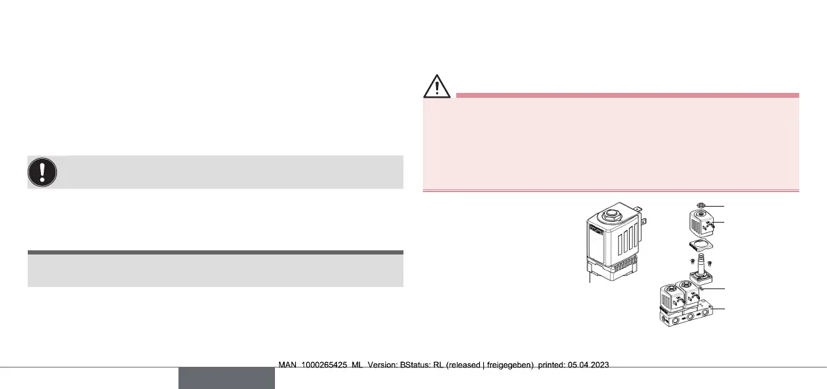
Valve with ange connection:
→ Remove cover plate.
→ Loosen nut and remove coil.
WARNING!
Danger due to escaping medium!
Leaking connections if the seals are not tted precisely, if the man-
ifold is uneven or if the surface quality of the manifold is inadequate.
▶ Make sure that the seals provided t the valve properly.
▶ Make sure that the manifold is even, with adequate surface
quality.
→ Insert the seal into the
valve body.
→ Screw valve body to
manifold (max. 1.5 Nm).
→ Mount coil and attach
nut (max. 5 Nm).
Seal
Nut
Coil
Cover plate
Manifold
English