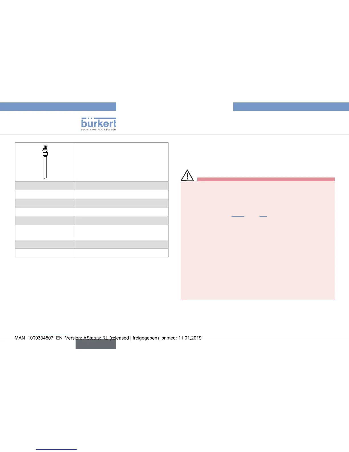
• 4 electrodes
• PG13.5 connection
• VarioPin male connector
Article number 563186
Measurement range
0.1...500000 µS.cm
–1
Linearity
1)
(relative)
±0.5...5 %
Cell constant
2)
0.360 cm
–1
Fluid temperature
–20...+150 °C. max
Fluid pressure
max. 20 bar (290 psi) at –20...+135 °C
max. 10 bar (145 psi) at +150 °C
Temperature sensor
Pt1000
Electrical connection
VarioPin (VP 6.0) male connector
1) Uncertainty of ±5 % arises when using only one single cell constant for the
full range. ±0.5 % measurement deviation can be achieved when calibration
is performed in a conductivity range close to that of the used solution.
2) Nominal cell constant.
Every product is measured according to a Bürkert standard procedure
and the individual cell constant measured is reported in the calibration
report, delivered with the product. The cell constant can be influenced by
the assembly situation.
6.5. Dimensions
→ Please refer to the technical data sheets related to the product
at: www.burkert.com
7. INSTALLATION
7.1. Safety instructions
danger
Risk of injury due to high pressure in the installation.
▶ Before any intervention on the installation, stop the circulation of
fluid, cut off the pressure and drain the pipe.
▶ Observe the dependency between the fluid temperature and the
fluid pressure. See Fig. 2 chap. 6.4.
Risk of burn injury due to electrical voltage.
▶ Observe all applicable accident protection and safety regula-
tions for electrical equipment.
Risk of burn injury due to high fluid temperatures.
▶ Do not touch with bare hands the parts of the product that are
in contact with the fluid.
▶ Before opening the pipe, stop the circulation of fluid and drain
the pipe.
Risk of injury due to the nature of the fluid.
▶ Respect the prevailing regulations on accident prevention and
safety relating to the use of dangerous fluids.
16
Installation
Type 8221