Do you have a question about the Burkert 8020 and is the answer not in the manual?
Indicates information that must be followed to avoid user danger or device malfunction.
Emphasizes reading the manual and ensuring product integrity and correct installation for safe operation.
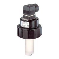
Explains the sensor's design, paddle-wheel mechanism, and signal generation principle.
Advises following specific installation guidelines from the fitting's manual and considering temperature-pressure limits.
Details the process of inserting the sensor into the S020 fitting system, emphasizing proper alignment and tightening.
Provides guidelines for cable selection, installation, and power supply for reliable signal transmission.
Step-by-step instructions for assembling the EN175301-803 cable plug for secure connection.
Details the wiring for the Hall effect sensor with dual NPN/PNP pulse outputs.
Explains the wiring for the Low Power Hall effect sensor with a single NPN pulse output.
Describes the wiring for the coil version sensor with a sinus output signal.
Illustrates typical connection setups for different sensor versions with control units.
Lists general physical and operational characteristics of the sensor, including pipe diameter and fluid properties.
Details electrical specifications for Hall effect and Low Power Hall versions, including voltage, current, and output data.
Lists the materials used for various components of the sensor, such as housing, finger holder, and gasket.
Specifies the operating temperature range, relative humidity, and housing protection rating (IP65).
Provides physical dimensions of the sensor with fitting S020 and a table of dimensions for various pipe diameters.
Lists conformity standards for electromagnetic compatibility, vibrations, and shock.
States the sensor is maintenance-free under normal conditions but provides cleaning instructions for contamination.
Lists order codes for common spare parts like gasket sets and cable plugs.
Provides order codes for complete sensor units based on power supply, gasket, sensor type, and connection.
Explains the meaning of the information and symbols present on the sensor's label.
Provides diagrams relating pipe diameter, flow rate, and fluid velocity for application selection.
| Material | Various (depending on version, e.g., PVC, PP, PVDF, stainless steel) |
|---|---|
| Output signal | 4...20 mA, frequency, relay, Modbus RTU, S0 pulse |
| Process connection | Various (depending on version, e.g., thread, weld, flange) |
| Power supply | 12...30 V DC |
| Type | Flowmeter |
| Voltage | 12...30 V DC |
| Protection class | IP65, IP67 (depending on version) |
| Connection type | Cable plug, terminal box |
| Housing material | PC |