19
Installation and wiring
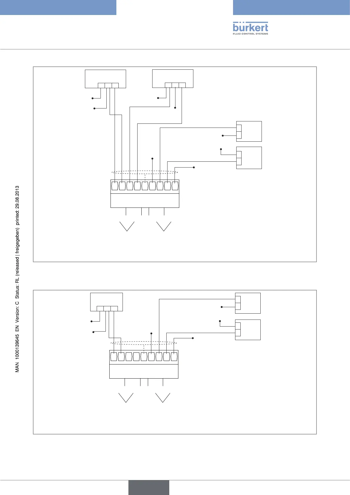
+-
1
A+
A-
A+
A-
FE
D+
D-
D+
D-
0 VDC
+
-
12-36 VDC
+
-
0 VDC
12-36 VDC
12-36 VDC
2 3 4 5 6 7 8 9
I
12-36 VDC
0 VDC
+-
I
0 VDC
(AI1) (AI2) (DI1) (DI2)
2nd digital output (at
external instrument)
1st digital output (at
external instrument)
1st 0/4-20 mA output
(at external instrument)
2nd 0/4-20 mA output
(at external instrument)
digital inputsanalogue
inputs
(designation in the configuration menus of the Mx
input module)
FE = functional earth
Figure 9 : Connecting the AI1 analogue input in source mode and the analogue input AI2 in sinking mode to a 3-wire
current transmitter (for example type 8025 with relay outputs) and connecting the digital inputs of the input
module
(designation in the configuration menus of the Mx
input module)
+-
1
A+
A-
A+
A-
FE
D+
D-
D+
D-
0 VDC
+
-
12-36 VDC
+
-
0 VDC
12-36 VDC
2 3 4 5 6 7 8 9
V
12-36 VDC
0 VDC
(AI1) (AI2) (DI1) (DI2)
2nd digital output (at
external instrument)
1st digital output (at
external instrument)
1st 0-5/10 V DC output
(at external instrument)
digital inputsanalogue
inputs
FE = functional earth
Figure 10 : Connecting the analogue inputs to a voltage transmitter and connecting the digital inputs of the input module
Type 8619
english