19
107774-01- 9/17
NOTICE
Do not exceed maximum vent/combustion air system length. Refer to Tables 7.1B, 7.5, 7.13, and 7.21
in this section for maximum vent/combustion air system length.
Use only vent and combustion air terminals and terminal locations shown in Tables 7.5, 7.13 and
7.21.
5. Minimum Vent and Air Intake Lengths - Observe the minimum vent lengths shown in Tables 7.5, 7.13 and 7.21.
6. Clearances to Combustibles - Maintain the following clearances from the vent system to combustible construction:
• Vent - 1/4” (also observe clearances through both combustible and non-combustible walls - see 9)
• Air Intake - 0”
• Concentric Portion of Concentric Terminals - 0”
7. Pitch of Horizontal Vent Piping - Pitch all horizontal vent piping so that any condensate which forms in the piping will run
towards the boiler.
• Pitch CPVC/PVC vent piping 1/4” per foot.
• Pitch Polypropylene vent piping 5/8” per foot.
VII. Venting A. Vent System Design (continued)
Table 7.1B: Vent/ Air Intake Fitting Equivalent Length
CPVC/PVC Fitting
Equivalent
Length (ft)
PolyPro, Polyue
or InnoFlue
Vent Fitting
Equivalent
Length (ft)
FasNSeal Vent Fitting
Equivalent
Length (ft)
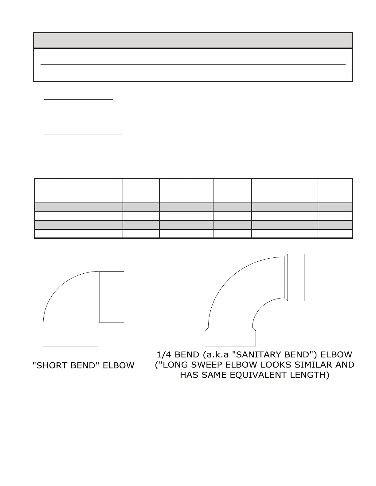
3” 90° Elbow (“Sanitary Bend”) 4.0 3” 90° Elbow 8.7
3” 90° Elbow 4.0
3” 45° Elbow 2.0 3” 45° Elbow 4.6
3” 45° Elbow 2.0
3” 90° Elbow (“Short Bend”) 10.0
3” Straight Tee 18.0
3” Coupling 0.0
3” Boot Tee 8.0
Figure 7.2: CPVC and PVC Elbows