8
107774-01 - 9/17
Table 2.2: Performance Specications
K2WTC Space Heating Ratings Domestic Hot Water (DHW) Ratings
1
Input, MBH
Hot Water Draw Limits, GPM
Model Number
Input, MBH
Heating
Capacity,
MBH
2
Net AHRI
Water,
MBH
AFUE, %
Max.
3
Min.
4
Min Max Min Max
70°F 77°F 90°F
Rise Rise Rise
K2WTC-135B 12 120 112 97 95.0 12 135 3.3 3.0 2.6 0.5
K2WTC-150B 15 150 142 123 95.0 15 150 3.9 3.7 3.1 0.5
K2WTC-180B 18 180 169 147 95.0 18 180 4.5 4.1 3.5 0.5
Notes:
1) DHW ratings are not AHRI certied.
2) The Net AHRI Water Ratings shown are based on a piping and pickup allowance of 1.15. The manufacturer should be consulted before selecting a boiler for
installations having unusual piping and pickup requirements, such as intermittent system operation, extensive piping systems, etc.
3) Maximum draw rates shown are at sea level and minimum vent length. Under other conditions draw rates will be reduced proportionally to the reduction in input. See
Table 2.4 and Appendix A for input de-rate information.
4) Minimum ow rate shown is that required through the boiler to initiate a call for DHW. A higher ow rate may be required through the xture due to mixing at the
tempering valve and xture itself.
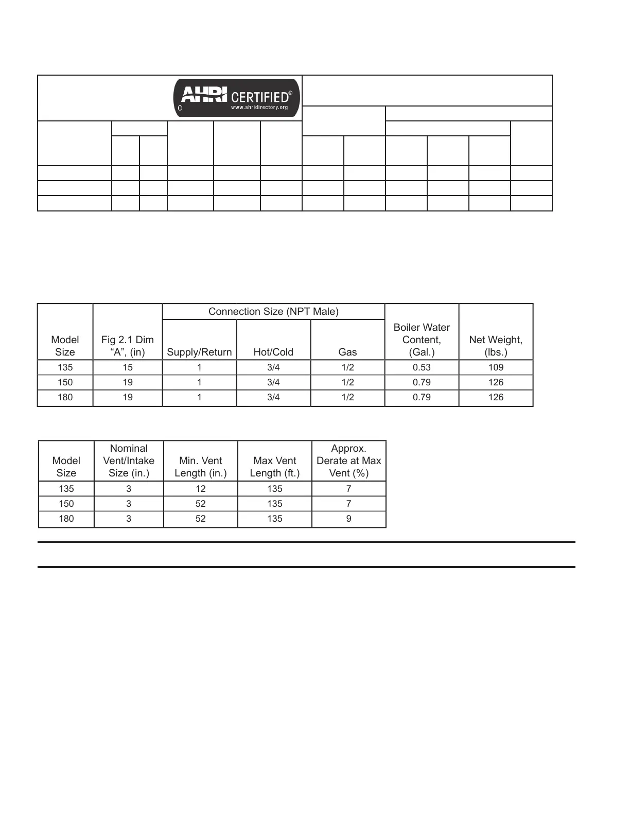
Table 2.3: Physical Specications
Model
Size
Fig 2.1 Dim
“A”, (in)
Connection Size (NPT Male)
Boiler Water
Content,
(Gal.)
Net Weight,
(lbs.)Supply/Return Hot/Cold Gas
135 15 1 3/4 1/2 0.53 109
150 19 1 3/4 1/2 0.79 126
180 19 1 3/4 1/2 0.79 126
1. Safe, reliable operation of this boiler depends upon installation by a professional heating contractor in strict accordance
with this manual and the requirements of the authority having jurisdiction.
• In the absence of an authority having jurisdiction, installation must be in accordance with this manual
and the National Fuel Gas Code, ANSI Z223.1. In Canada, installation must be in accordance with the B149.1
Installation Code.
• Where required by the authority having jurisdiction, this installation must conform to the Standard for Controls
and Safety Devices for Automatically Fired Boilers (ANSI/ASME CSD-1).
2. Read Section VII to verify that the maximum combustion air and exhaust pipe lengths will not be exceeded in the
planned installation. Also verify that the vent terminal can be located in accordance with Section VII.
3. Make sure that the boiler is correctly sized:
• For heating systems employing convection radiation (baseboard or radiators), use an industry accepted sizing
method such as the I=B=R Guide RHH published by the Air-Conditioning, Heating and Refrigeration Institute
(AHRI).
III. Before Installing
II. Specications (continued)
Table 2.4: Vent Lengths
Model
Size
Nominal
Vent/Intake
Size (in.)
Min. Vent
Length (in.)
Max Vent
Length (ft.)
Approx.
Derate at Max
Vent (%)
135 3 12 135 7
150 3 52 135 7
180 3 52 135 9