60
107774-01 - 9/17
VII. Venting H. Assembly of Centrotherm InnoFlue Vent Systems
H. Assembly of Centrotherm InnoFlue Vent Systems
1. This boiler has been approved for use with the Centrotherm InnoFlue single wall Polypropylene vent system to be provided
by the installer.
WARNING
Asphyxiation Hazard. Follow these instructions and the installation instructions included by the
original Polypropylene venting component manufacturers, Centrotherm. Failure to do so could cause
products of combustion to enter the building, resulting in severe property damage, personal injury
or death. Where a conict arises between Centrotherm instructions and these instructions, the more
restrictive instructions shall govern.
Do not mix vent components or joining methods for listed manufacturers.
Examine all components for possible shipping damage prior to installation.
All condensate that forms in the vent must be able to drain back to the boiler.
2. Assemble the vent system, starting at the boiler:
a. The vent adaptor has three different inside diameters. The middle inside diameter accepts 3” nominal InnoFlue (Figure
7.27). A locking band clamp in the adaptor prevents the vent pipe from coming out of the adaptor once it is installed
andtightened.Lubricatetheuppergasketintheventadaptorwithwaterandinserttherstpieceof3”InnoFlueintothe
adaptor until it bottoms out. Tighten locking band clamp to secure vent pipe.
b. Assemble the next piece of 3” InnoFlue.
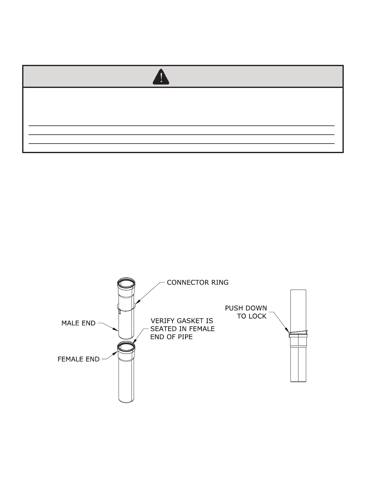
c. For each joint, verify that the gasket is evenly seated in the bell (female) end of the pipe. Lubricate this gasket with
Centrocerin # IACE50. Slide a connector ring over the male end of the pipe to be joined as shown in Figure 7.44. Push
the male end of the next section of pipe into the bell until it bottoms out, then back out 1/4” to provide room for thermal
expansion.PushhookonconnectingringoverthebellendoftherstsectionofpipeasshowninFigure7.44.
d. Assemble the rest of the vent system per the manufacturer’s installation instructions, being sure to pitch horizontal
sections back towards the boiler 5/8”/ft.
e. Support each horizontal pipe section with a minimum of one wall strap each and at intervals not exceeding 39in.
Figure 7.44: InnoFlue Connector Ring Installation