73
107774-01- 9/17
C. Near Boiler Piping Design
ProperoperationofthisboilerrequiresthatthewaterowratethroughitremainwithinthelimitsshowninTable9.1
anytimetheboilerisring.Atowratesbelowtheminimumshown,theboiler’sowswitchand/ortemperatureriselimit
functionmaypreventtheboilerfromring.FlowratesthroughtheboilerinexcessofthemaximumshowninTable9.1can
result in excessive noise or erosion damage to piping
There are two basic methods that can be used to pipe this boiler into the system. Method #1 (primary-secondary piping)
is always preferred. Additional information on hydronic system design can be found in the I=B=R Guide RHH published by
the Air-Conditioning, Heating and Refrigeration Institute (AHRI).
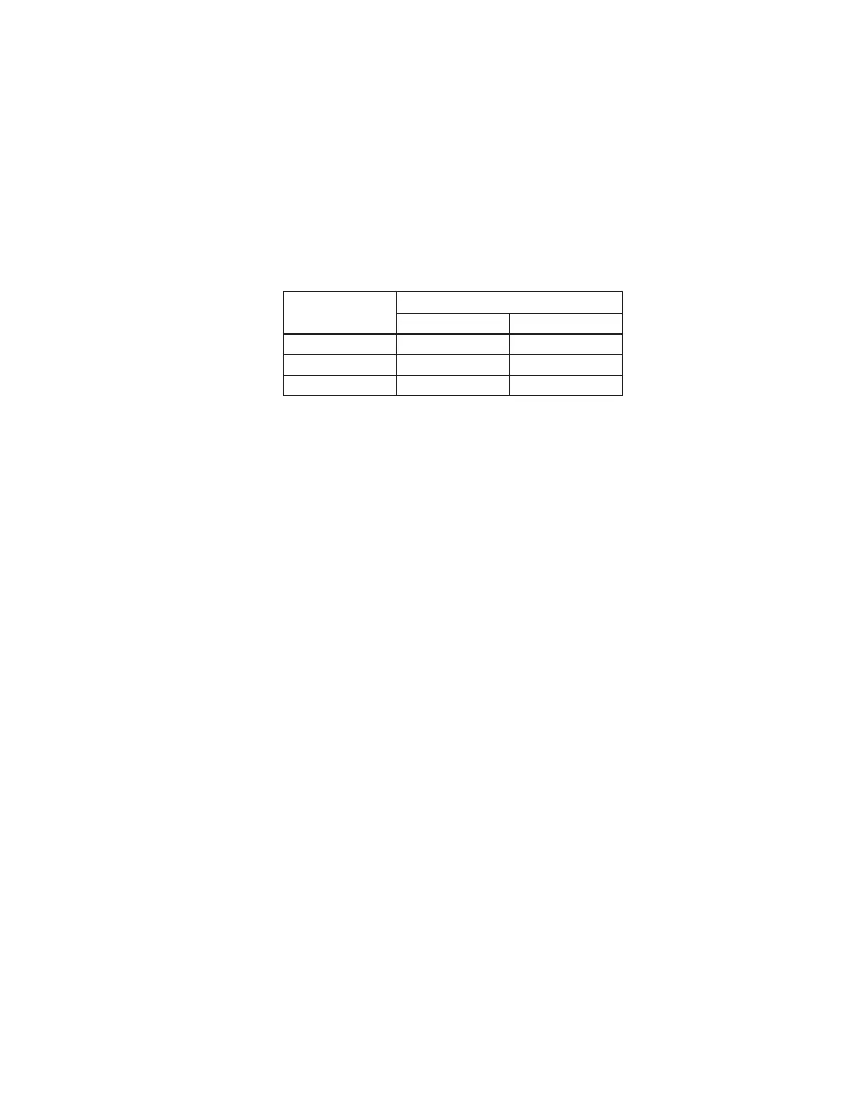
Table 9.1 Water Flow Rate Limits
Model
Flow (GPM)
Minimum Maximum
135 6.2 13.3
150 7.7 13.3
180 9.3 13.3
Method 1: Primary/Secondary Piping (Strongly Recommended)
ThismethodisshowninFigure9.2.Inthissystem,theowratethroughtheboiler(“secondaryloop”)iscompletely
independentoftheowratethroughthesystem(“primaryloop”).Usethefollowingguidelinestoensurethattheboilerwill
havetherequiredowshowninTable9.1regardlessoftheowintheheatingsystem.
1.SystemLoopPiping-Sizethesystemcirculatorandpipingtoobtainthedesignowratethroughtheheatingsystem
as you would on any other heating system. All piping between the expansion tank and secondary connection tees must
beatleast1”.Inordertokeeptheowratesinthesystemandboilerloopsindependentofeachother,provideatleast
8diametersofstraightpipeupstreamoftherstteeand4diametersdownstreamofthesecondtee.Keepthedistance
betweentheexpansiontankandtherstsecondaryteeasshortaspractical.
2.BoilerLoopPiping–AllboilersaresuppliedwithabuiltincirculatorwhichwilldelivertheowrequiredbyTable9.1
provided both of the following conditions are met:
• All piping in the boiler loop has a nominal size of at least 1”
• The equivalent length of all piping in the boiler loop is 60 ft or less.
To verify that the 60 ft, equivalent length is not exceeded, do the following:
a.Countallttingsintheplannedboilerloop(theshadedpipinginFigure9.5).
b.UsingTable9.3,ndtheequivalentlengthsofallttingsinthesecondaryloop.Totaltheseequivalentlengthsand
add them to the total length of planned straight pipe in the secondary loop.
c. The result is the total equivalent length of the planned boiler loop. If the equivalent length calculated in (b) is
underthelimitshowninTable9.4,theboilerpumpwillachieveaowrateandtemperatureriseapproximately
equal to that shown in this table. Otherwise, the equivalent length must be reduced.
IX. System Piping (continued)