72
107774-01 - 9/17
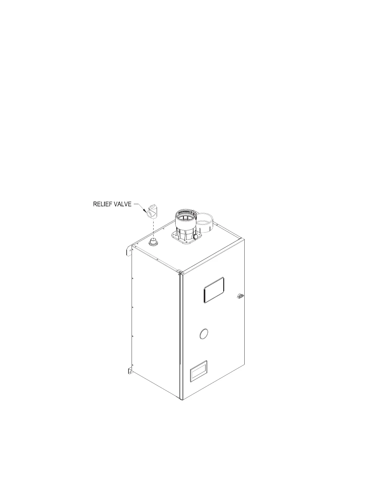
Figure 9.0: Factory Supplied Piping and Trim Installation
IX. System Piping (continued)
9. Drain Valve (required) – Install the drain valve (provided by the installer) as shown in Figure 9.2.
10. Low Water Cut-off (may be required by local jurisdiction) – Protection of this boiler against low water and/or
inadequateowisprovidedbytheUL353certiedowswitchbuiltintotheboiler.Thisisawatertubeboilerand
thisowswitchisthereforetheonlyeffectivewaytoprovidesuchprotection.SectionHG614(c)ofthe2015
ASMEboilerandPressureVesselCoderecognizestheuseofalistedowswitchinlieuofalowwatercut-offon
water tube boilers.
In the event that a local jurisdiction insists upon the installation of a low water cut-off with this boiler, refer to Part
XI and the low-water cut-off manufacturer’s instructions for proper wiring. Install the low water cut-off in the supply
piping at the point prescribed the local jurisdiction (generally at a point above the boiler).
If a probe type low water cut-off is used, be certain that it is located at a point in the piping from which air can
escape to an automatic air vent. Generally, this means that there should be no down-turns in the piping between
the low water cut-off and the point where the automatic air vent is installed. Failure to do this may result in nuisance
boiler shut-downs due to small amounts of air trapped around the probe.