23
107774-01- 9/17
VII. Venting B. Design Requirements Unique to Horizontal Twin Pipe Venting Systems (continued)
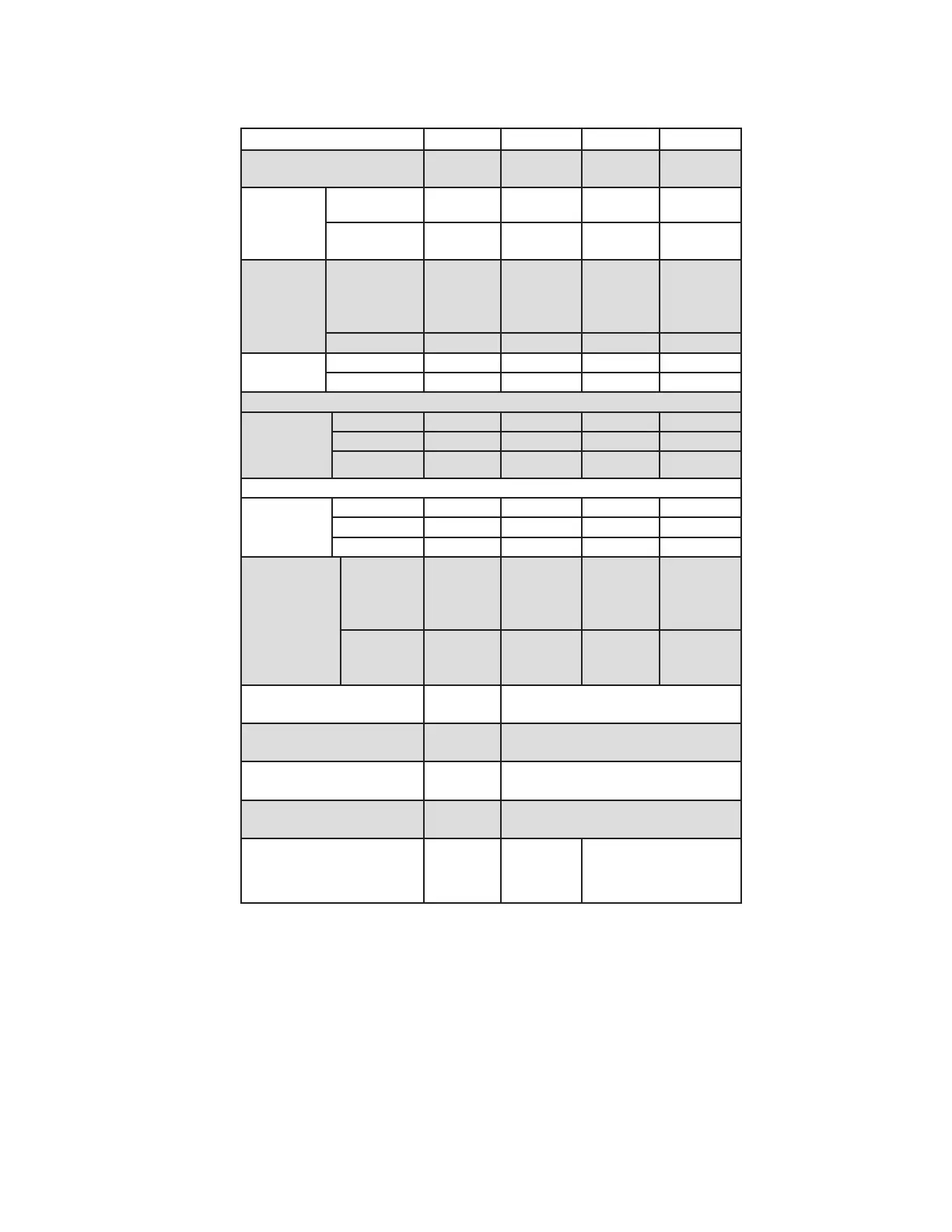
Table 7.5: Summary of Horizontal Twin Pipe Venting Options
Vent Option 1 2 3 4
Illustrated in Figure
7.6, 7.7,
7.8
7.9, 7.10 7.9 7.9
Pipe
Penetration
through
Structure
Vent Wall Wall Wall Wall
Intake Wall Wall Wall Wall
Material
Vent
CPVC/
PVC
(Note 2)
DuraVent
PolyPro
(Rigid)
Selkirk
Polyue
Centro-
therm
InnoFlue
SW
Intake PVC PVC PVC PVC
Nominal
Diameter
Vent 3” 3” 3” 3”
Intake 3” 3” 3” 3”
Min Equivalent Vent Length:
Models
135 12” 12” 12” 12”
150 52” 52” 52” 52”
180 52” 52” 52” 52”
Max Equivalent Vent Length (Note 1):
Models
135 135ft 135ft 135ft 135ft
150 135ft 135ft 135ft 135ft
180 135ft 135ft 135ft 135ft
Terminal
Option A
(Fittings)
Vent
Coupling
w/screen
(Note 3)
3PPS-12B
or
3PPS-36B
w/screen
3PF-10UV
or
3PF-39UV
w/screen
ISEP03 or
ISEP0339
w/screen
Intake
Elbow
w/screen
(Note 3)
Elbow
w/screen
Elbow
w/screen
Elbow
w/screen
Terminal Option B
(Ipex Low Prole)
Ipex
#196985
Not Permitted
Terminal Option C
(DiversiTech HVENT)
HVENT-3 Not Permitted
Terminal Option D
(Ipex FGV Concentric)
Ipex
196006
Not Permitted
Terminal Option E
(DiversiTech CVENT)
CVENT-3 Not Permitted
Terminal Option F
(DuraVent Horizontal
Concentric)
Not
Permitted
3PPS-HK Not Permitted
Notes:
1. Max vent lengths shown also apply to the intake. For example, Vent Option #1 may have up to 135ft of vent pipe and also up to
135 ft of intake pipe.
2. First 30” of vent and vent Elbow connected to boiler must be CPVC. Downstream vent pipe can be PVC except as noted in text.
3. PVC Terminal coupling and inlet elbow may be offset on snorkels as shown in Figure 7.12.