95
107774-01- 9/17
11) Start the boiler using the lighting instructions on page 100. With the boiler powered up, and with no call for heat, the
display should look like Figure 12.2a. Once a call for heat is present, it will look like Figure 12.2b.
12) Theboilershouldattempttoreapproximately30secondsafteracallforheatappears.Withthefrontdooropen,this
try for ignition will appear as an audible spark (lasting approximately 4 seconds) and an audible click from the gas
valve.Uponinitialstart-up,thegastrainwillbelledwithair.Evenifthegaslinehasbeencompletelypurgedofair,
itmaytakeseveraltriesforignitionbeforeaameisestablished.Iftheboilerdoesnotlightaftersixtriesforignition,
it will enter a “soft lockout” and will wait for one hour before attempting another ignition sequence. This soft lockout
canberesetbyinterruptingpowertotheboilerforafewseconds.Onceaamehasbeenestablishedforthersttime,
subsequentcallsforburneroperationshouldresultinaameonthersttry.
13) Ifthereisaproblemthatappearsbeforethersttryforignition,oriftheboilerfailstolightaftersixtriesforignition,the
blinking “HELP” button is highlighted on the Home screen (Figure 12.2c). Touching this “HELP” button will take the
usertotheDiagnosticsmenuwherethecauseoftheproblemcanusuallybefoundbypressingtheashingbuttononeach
successive screen.
14) Inspecttheamevisiblethroughthewindow.Onhighretheameshouldbestableandmostlyblue(Figure12.3).No
yellowtippingshouldbepresent;however,intermittentecksofyellowandorangeintheamearenormal.
15) Check the inlet gas pressure. Verify that the inlet gas pressure is between the upper and lower limits shown on the rating
plate with all gas appliances on and off.
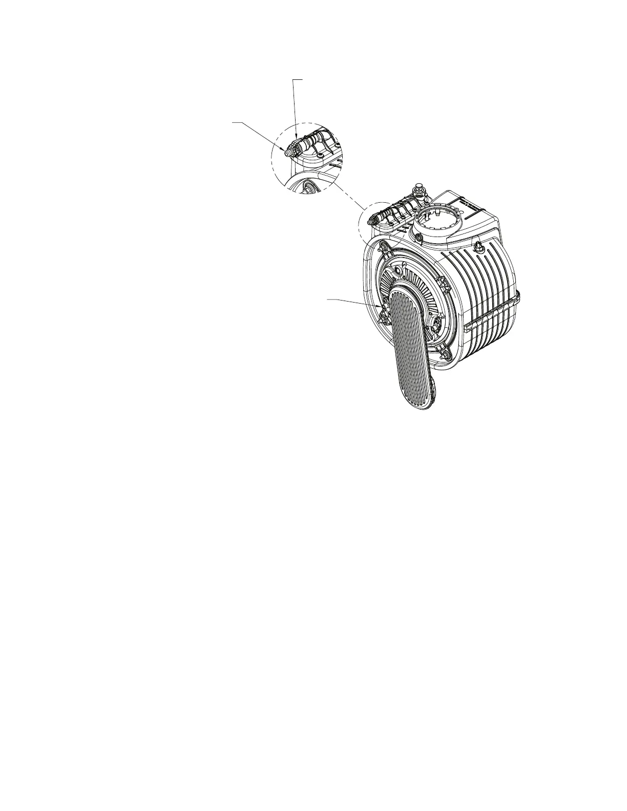
Figure 12.1: Location of Manual Air Vent
XII. Start-Up and Checkout (continued)
FLAME ROD
ATTACH 1/4" ID CLEAR
TUBING TO HOSE BARB
AND ROUTE TO SAFE PLACE
AWAY FROM CONTROLS
BEFORE OPENING VENT.
MANUAL AIR VENT