Installation | 4
Instruction Manual VACTEST DCC 400_EN_en 9 / 24
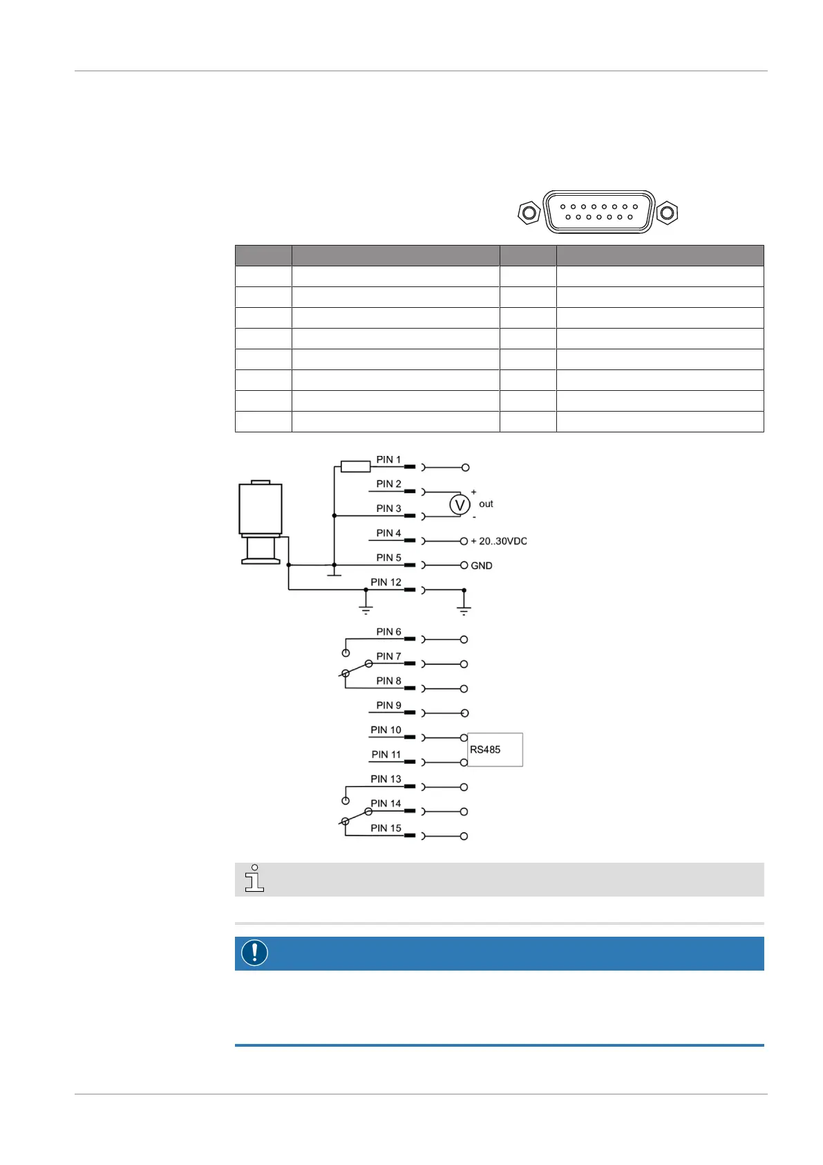
4.3.3 I/O and Communication Port Schematic
The electrical connection is to be made by means of suitable cables considering EMI de-
mands and according to the pin description shown below:
Connector: D-Sub15, 15-pin, male
Pin no. Description Pin no. Description
1 Identification 2 Signal Output 0 … 10 VDC
3 AGND 4 Voltage Supply 24 VDC
5 Supply GND 6 Relay 1, NO (normally open)
7 Relay 1, Common 8 Relay 1, NC (normally closed)
9 N/A 10 RS485, D+
11 RS485, D- 12 Ground
13 Relay 2, NO (normally open) 14 Relay 2, Common
15 Relay 2, NC (normally closed)
NOTE
We recommend to have "Ground" (Pin 12) and supply common (Pin 5) grounded.
NOTICE
Incorrect supply voltage.
Risk of damage to the device!
• Make sure to supply a correct and admissible voltage.