INSTRUCTION, USE AND
MAINTENANCE MANUAL
GB
Page 17 of 67
• The inflation pressure gauge “M” displays the pres-
sure into the tyre.
11.2 Computer
The machine is equipped with a computer checking
and controlling the automatic cycle operations of tyre
mounting and demounting from the rim.
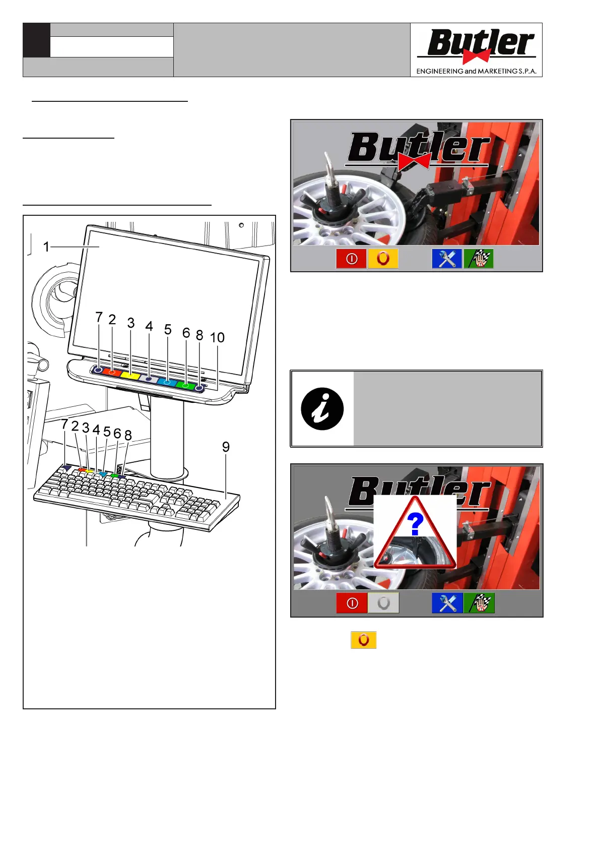
11.2.1 Control panel description
KEY
1 – Monitor
2 – Function push button (red) (F1)
3 – Function push button (yellow) (F2)
4 – Function push button (grey) (F3)
5 – Function push button (blue) (F4)
6 – Function push button (green) (F5)
7 – Esc” push button (Esc)
8 – More” push button (F6)
9 – Push-button panel for data entry
10 – Rapid functions push-button panel
(keyboard with 7 keys)
Fig. 15
CAPTURE 4 - CAPTURE 4 FI
7104-M007-4_B
When tyre-changer is started up, the main screen page
of the machine (Home) is displayed:
Coloured boxes with icons representing precise func-
tions are displayed in the bottom part of the main
screen page and of each page afterwards described.
When the corresponding coloured push button on the
“rapid functions push-button panel” (Fig. 15 ref. 10)
or on the “data entry push-button panel” (Fig. 15
ref. 9) is pressed, these functions are enabled.
IN CASE OF TYRE-CHANGER
ANOMALOUS SHUTDOWN (NOT
THROUGH “PC SHUTDOWN” KEY),
THE “EMERGENCY” STARTUP PIC-
TURE IS DISPLAYED, AS SHOWN
BELOW.
The main screen page displays a blinking triangle, and
push button
is disabled. push buttons (Fig. 14
ref. B-C) are also disabled.
Only the vertical translation movements of the four
arms (Fig. 14 ref. E-F-G-H) and the mandrel rotation
(Fig. 16 ref. A) will be enabled.