INSTRUCTION, USE AND
MAINTENANCE MANUAL
GB
Page 29 of 67
To lock a rim proceed as follows:
1. Dowel the wheel (Fig. 19 ref. 1) on the rubber plate
and check that the dragging pin (Fig. 19 ref. 2)
enter in a hole placed on the rim hub.
Fig. 19
IF THE WHEEL HUB IS HIGH-
ER THEN THE DRAGGING PIN
(FIG. 20 REF. 2), USE THE EXTEN-
SION (FIG. 20 REF. 1) SUPPLIED
ON ISSUE.
Fig. 20
FOR WHEELS WITH ALLOY RIMS,
USE THE PROPER PLASTIC GUARD
(FIG. 21 REF. 1).
Fig. 21
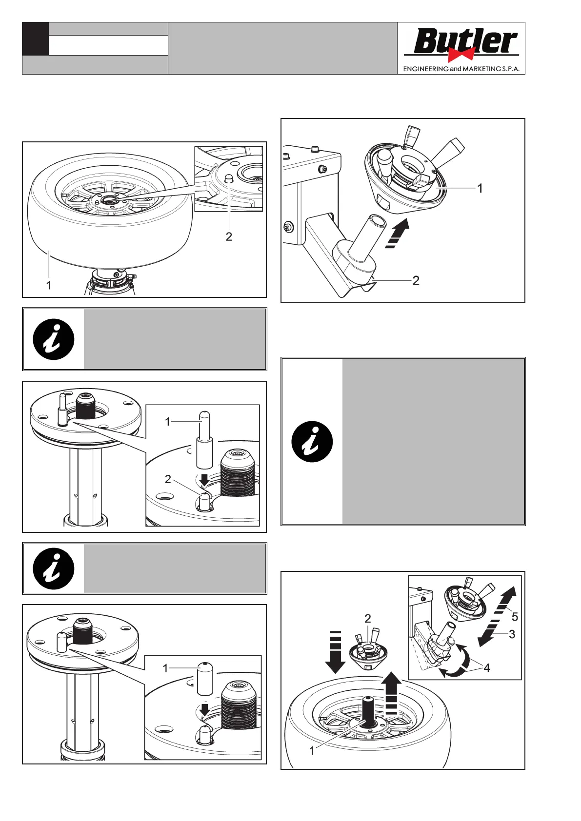
2. Remove the locking ring nut (Fig. 22 ref. 1) from
the activator support (Fig. 22 ref. 2).
Fig. 22
3. By removing the locking ring-nut (Fig. 22 ref. 1)
from the activator support (Fig. 22 ref. 2), the
central threaded shaft (Fig. 23 ref. 1) lifts auto-
matically until its maximum height.
AFTER A DEFAULT MANUFACTUR-
ING TIME, THE THREADED SHAFT
(Fig. 23 ref. 1) RETURNS TO ITS
OWN HOUSING. IF THE LOCKING
RING-NUT HAS NOT BEEN IN-
SERTED YET, IT IS POSSIBLE TO
MAKE IT COME OUT AGAIN, BY
ACTIVATING MANUALLY THE AC-
TIVATOR SUPPORT (Fig. 23 ref. 4)
OR BY REPOSITIONING (Fig. 23
ref. 3) AND THEN, GRABBING THE
(Fig. 23 ref. 5) LOCKING RING-
NUT FROM ITS OWN SUPPORT, AS
INDICATED IN FIG. 23.
4 - Insert and block the ring-nut (Fig. 23 ref. 2) on
the threaded shaft (Fig. 23 ref. 1) as described
hereafter.
Fig. 23
CAPTURE 4 - CAPTURE 4 FI
7104-M007-4_B