Do you have a question about the C-TEC EP203 and is the answer not in the manual?
Details the guarantee terms for the equipment installation and commissioning.
Emphasizes consulting qualified personnel for system design and installation regulations.
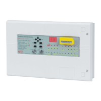
Describes the components of the EP203 panel enclosure and its parts.
Provides step-by-step instructions for safely removing panel components for installation.
Guidelines for selecting an indoor location and mounting the EP203 panel enclosure.
Details the requirements for connecting the mains supply to the EP203 panel.
Explains how to wire conventional detector circuits to the EP203 panel.
Details the wiring for conventional polarised sounder circuits to the EP203 panel.
Describes the wiring for six monitored input connections on the EP203 panel.
Explains the wiring for the six auxiliary relay outputs provided by the EP203 panel.
Details how to remotely control EP203 panel functions via input connections.
Specifies wiring for extinguishant output circuits, supporting solenoids or Metrons.
Provides wiring diagrams and resistance requirements for one or two solenoid connections.
Details wiring for igniting actuators, including resistance limits and diagrams.
Explains wiring connections for Remote Status Units (RSUs) and Economy Status Units (ESUs).
Guidance on selecting and using appropriate cables for system wiring and regulations.
Instructions for planning cable entry and internal distribution within the EP203 panel.
Prepares the panel by checking connections and cable integrity before energizing.
Instructions for physically mounting and securing the Power Supply and Expansion Relay Boards.
Details the final steps for connecting the mains supply to the Power Supply PCB.
Guides on mounting and securing the Main Control PCB and its connections.
Explains how to connect various circuits to the Main Control PCB connector blocks.
Describes functions available to general users, including manual activation and sounder muting.
Outlines functions for authorised users, including silencing sounders and resetting alarms.
Details functions exclusively for engineers, including commissioning and system engineering.
Provides step-by-step instructions for navigating and using the engineer-level menus.
Provides a summary of the menus and sub-menus available in Access Level 3.
Details options for temporarily disabling system components like zones, sounders, and relays.
Covers panel settings for zone selection, delays, durations, and extract options.
Includes functions for walk tests, relay testing, sounder testing, PSU stats, and version numbers.
Explains how faults are indicated on the EP203 panel via LEDs, sounder, and LCD display.
Diagnoses open/short circuit faults on detection zones, including suggested actions.
Details diagnosis for open/short circuit faults on sounder circuits and suggested actions.
Covers faults related to mains/battery supply, fuses, and PSU status.
Diagnoses system-wide faults like watchdog, memory corruption, and PCB issues.
| Zones | 2 |
|---|---|
| Standards Compliance | EN54-2, EN54-4 |
| Product Type | Fire Alarm Panel |
| Supply Voltage | 230V AC |
| Auxiliary Power Output | 24V DC |
| Sounders Supported | Conventional sounders |
| Detectors Supported | Conventional detectors |
| Weight | 3.5kg |