EP203 AUTOMATIC EXTINGUISHER PANEL
Page 20 of 45 • EP203 AUTOMATIC EXTINGUISHER PANEL INSTALLATION MANUAL • Approved Document No. DFU0002032 Rev 4
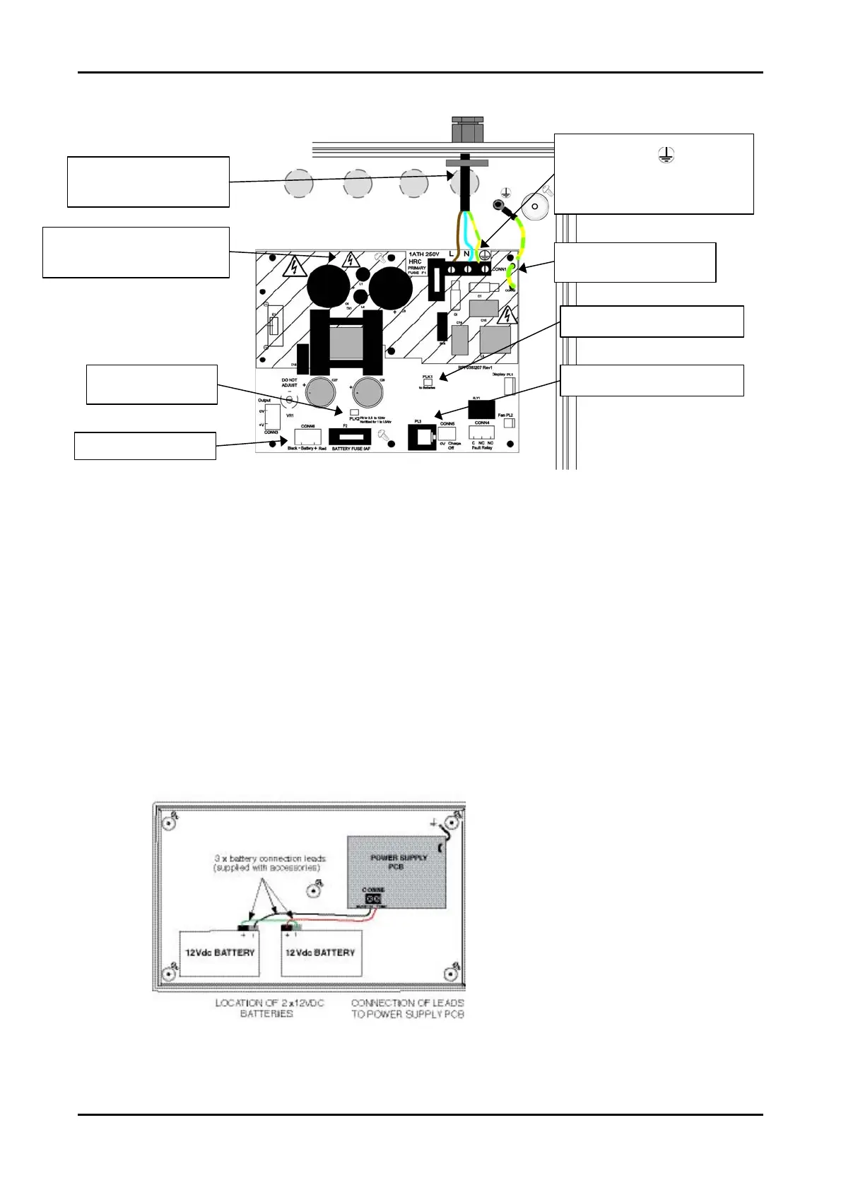
Figure 12 : Power Supply PCB Layout and Connection Details
Connecting the Standby Batteries
CAUTI ON : Alway s di sp ose o f used batter ie s in accordance w ith the battery
manufacturer s ’ ins t ruc ti o ns. There i s a r i sk of ex pl osion i f bat ter ies are
replaced by an i ncorrect ty pe .
Two, new high quality and fully charged 12Vdc, 7Ahr valve regulated lead-acid (VRLA)
type batteries are required as the emergency standby power supply for the EP203
panel. The capacity of the batteries may be lesser-rated dependant upon the required
standby time. To calculate the batteries required for any given standby period, refer to
the calculation guide in Appendix 1.
The batteries should be connected in series and located in the EP203 panel’s enclosure
as shown in Figure 13, below.
Note: The battery connection leads (red
lead, black lead and green link wire) are
supplied in the accessory pack.
The EP203 panel’s sophisticated battery
monitoring unit protects the batteries
against deep discharge by activating a
cut off circuit when the standby supply
voltage reaches approx. 21Vdc. If
batteries are not fitted, are discharged,
or in poor condition, a PSU fault will be
displayed at the EP203 panel.
Figure 13 : Battery Location and Connection Details
Mains In put (CO N N1)
L = Live, N = Neutral, = Earth
CLASS 1 EQU IPMENT M UST BE
EARTHED. Connect incoming mains earth
wire to the earth terminal and NOT to
the base earth post.