EP203 AUTOMATIC EXTINGUISHER PANEL
Page 18 of 45 • EP203 AUTOMATIC EXTINGUISHER PANEL INSTALLATION MANUAL • Approved Document No. DFU0002032 Rev 4
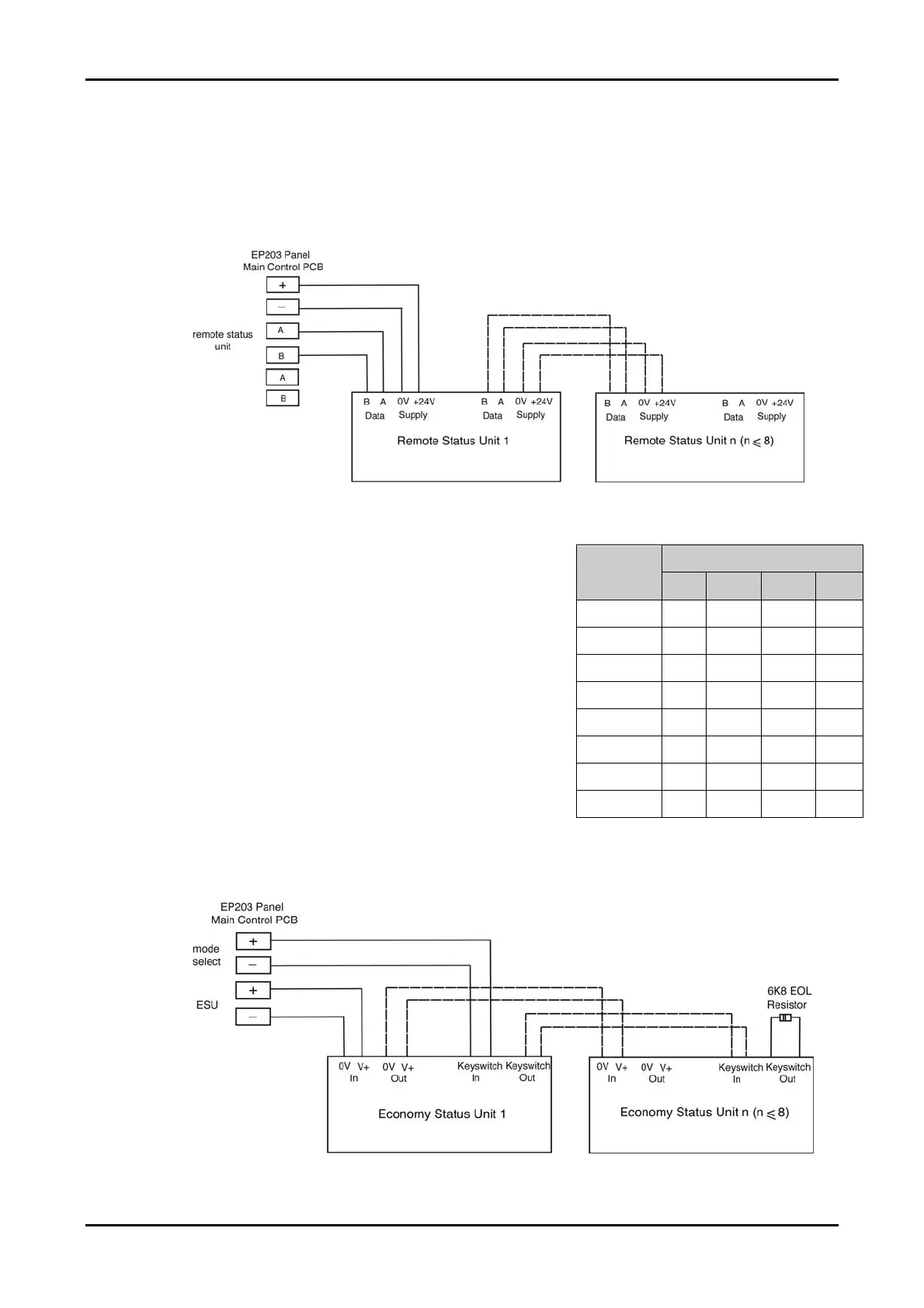
Connection to RSUs and ESUs
RSUs require a 4-wire connection (2-wire power, 2-wire RS485) from the EP203 panel
that connects to each unit and is daisy chained onto the next (see Figure 10 below).
The RSU abbreviated functions at the Main Control PCB are listed below:
• +/ – : 2-wire power supply (24V); A/ B: 2-wire RS485 data connection
Figure 10 : Typical RSU Circuit Wiring
Each RSU has a pcb-mounted DIL switch and must be
allocated a unique address between 1 and 8. See
right for DIL switch settings (=DIL switch ON/UP).
Each RSU has a pcb-mounted Display Contrast (VR1)
that can be adjusted to suit the contrast of the
units’ LCD display.
ESUs require a 2-wire 24V power connection and
2-wire mode select from the EP203 panel that
connects to each unit and is daisy chained onto the
next (see figure 11 below).
A 6k8 end-of-line resistor (supplied in the accessory
pack) must be connected across the terminals of the
last ECU on each circuit to allow the wiring to be
line monitored for open and short circuit faults.
Note: Unused circuits must have a 6k8 resistor fitted at the EP203 panel terminals.
Figure 11 : Typical ESU Circuit Wiring