EP203 AUTOMATIC EXTINGUISHER PANEL
Page 8 of 45 • EP203 AUTOMATIC EXTINGUISHER PANEL INSTALLATION MANUAL • Approved Document No. DFU0002032 Rev 4
• System expansion connections for the following add-ons:
O ut put Expansi on Rela y Board - Pa rt No. EP212
a) One Output Expansion Relay Board can be connected.
b) Provides up to five volt-free relay outputs (Reset, Mode, Discharged, Hold, Abort).
c) Mounted inside the EP203 panel.
d) Instruction document no. DFU0000212.
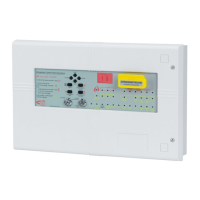
Remote Statu s Uni t (RS U) - Part N o. EP210S /EP210F
a) Up to eight RSUs can be connected.
b) Provides remote indication of system status.
c) Flush-mounted (EP210F), or surface-mounted (EP210S).
d) Mode (Manual, or Manual & Automatic).
e) Manual release of extinguishant.
f) 128 x 64 pixel graphic LCD unit with two-colour backlight.
g) Three monitored inputs (Abort, Hold and Mode).
h) 2-wire RS485 + 2-wire power (24V).
i) Instruction document no. DFU0000210.
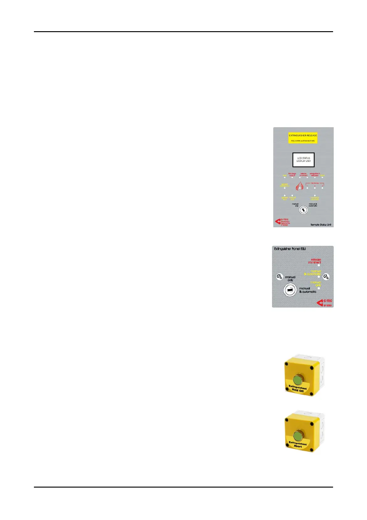
Economy Statu s Uni t (ES U) - Part No. EP211
a) Up to eight ESUs can be connected.
b) Provides remote indication of extinguishant “release
imminent”.
c) Single-gang mounting arrangement.
d) Mode (Manual, or Manual & Automatic).
e) 2-wire power (24V) + 2-wire mode select
f) 6K8 EOL resistor fitted in last EP215 allows wiring to be
monitored for open and short-circuit faults
g) Instruction document no. DFU0000211.
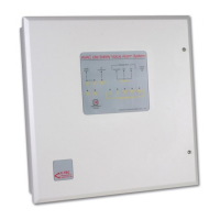
Sy s tem Hold O ff / Abo rt But ton - Part No. EP215
a) Monitored input to the EP203 panel.
b) Used to either delay, or cancel the extinguishant release
sequence (dependent on connection to EP203 panel).
c) Connects to EP203 panel via 2-wire connection. The
remaining EP215 units are then daisy-chained.
d) Single-gang, surface-mounted unit.
e) 6K8 EOL resistor fitted in last EP215 allows wiring to be
monitored for open and short-circuit faults.
f) Instruction document no. DFU0215000.