17
5 Adjustments
The set values for the winding torque and the resulting pulling force at the test collar are:
Winder Measurement Direction of rotation Winding torque M Pulling force F
Ribbon rewinder A against winding direction 12,9 - 13,5 Ncm 4,3 - 4,5 N
B in winding direction 2,1 - 3,0 Ncm 0,7 - 1,0 N
Ribbon unwinder C any 3,6 - 4,5 Ncm 1,2 - 1,5 N
Table 1 Winding torques at the transfer ribbon winders
1
2
3
4
1
A B
1
C
2
3
4
5
5
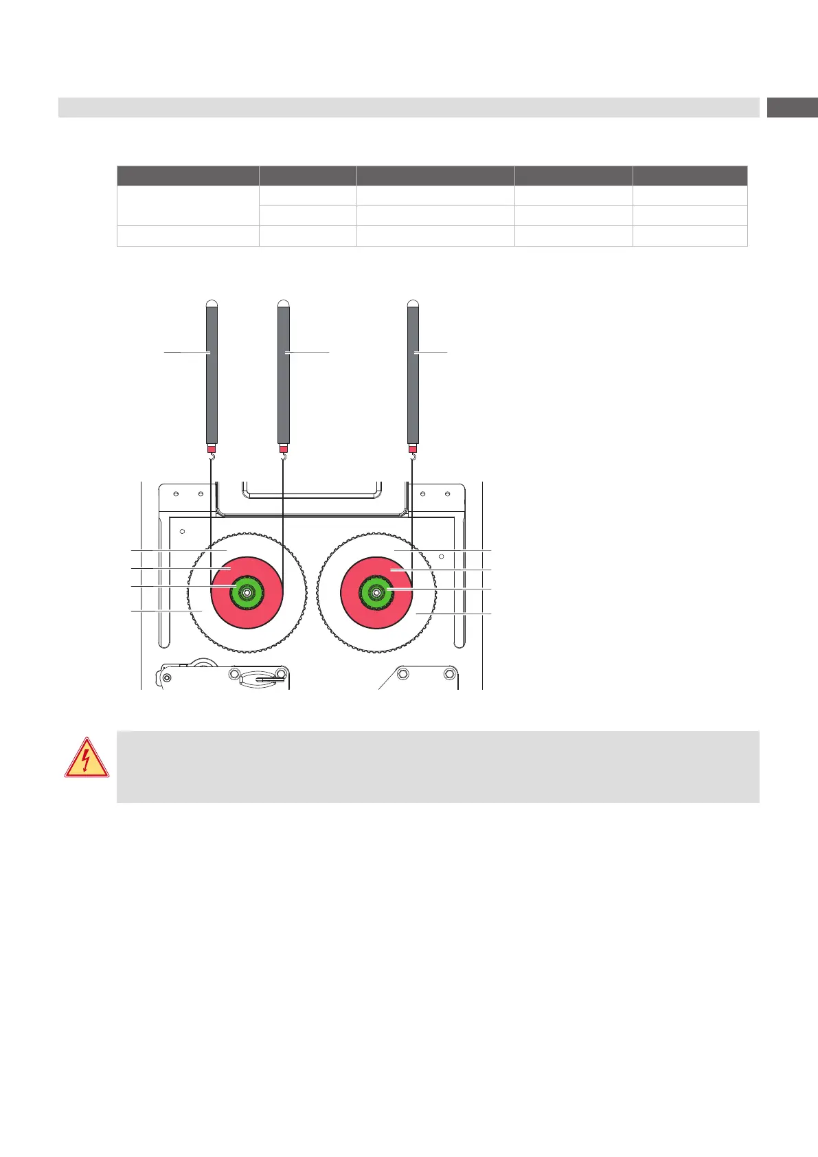
Figure 13 Measuring the winding torques
Danger!
Risk of death via electric shock!
Before opening the rear cover, disconnect the device from the mains supply and wait at lease one
minute until the power supply unit has discharged.
1. Unplug the printer from the electrical outlet.
2. Remove the rear cover 2.2 on page 6.
3. Remove the transfer ribbon from the printer.
4. Attach the test collar (3) to the winder (5).
5. Turn the knurled nut (4) counterclockwise to clamp the test collar.
6. Wind the cord attached to the test collar around the test collar several times.
7. Secure spring scale [10 N] (1) at the end of the cord.
8. Move the spring scale upward vertically until the winder begins to turn.
9. Hold the drive belt in place during the measurement. Otherwise, the measurement is not accurate.
10. Allow the cord to unwind from the test collar at least one full turn and read the pulling force F on the spring scale
at the same time.
11. If the winding torque differs from the set value, it must be adjusted 5.1.2 on page 18.
 Loading...