22 22
5 Adjustments
5.2.5 Adjusting the Transfer Ribbon Feed Path
The transfer ribbon feed path can be affected by the following adjustments:
Method Purpose
Fine-tuning of the printhead pressure Avoiding wrinkles in the print zone arising from the inner or outer side
Bowing the printhead Avoiding wrinkles in the print zone arising from the middle
Adjusting the ribbon deection Adapting the feed path to the print image
Table 2 Adjusting the transfer ribbon feed path
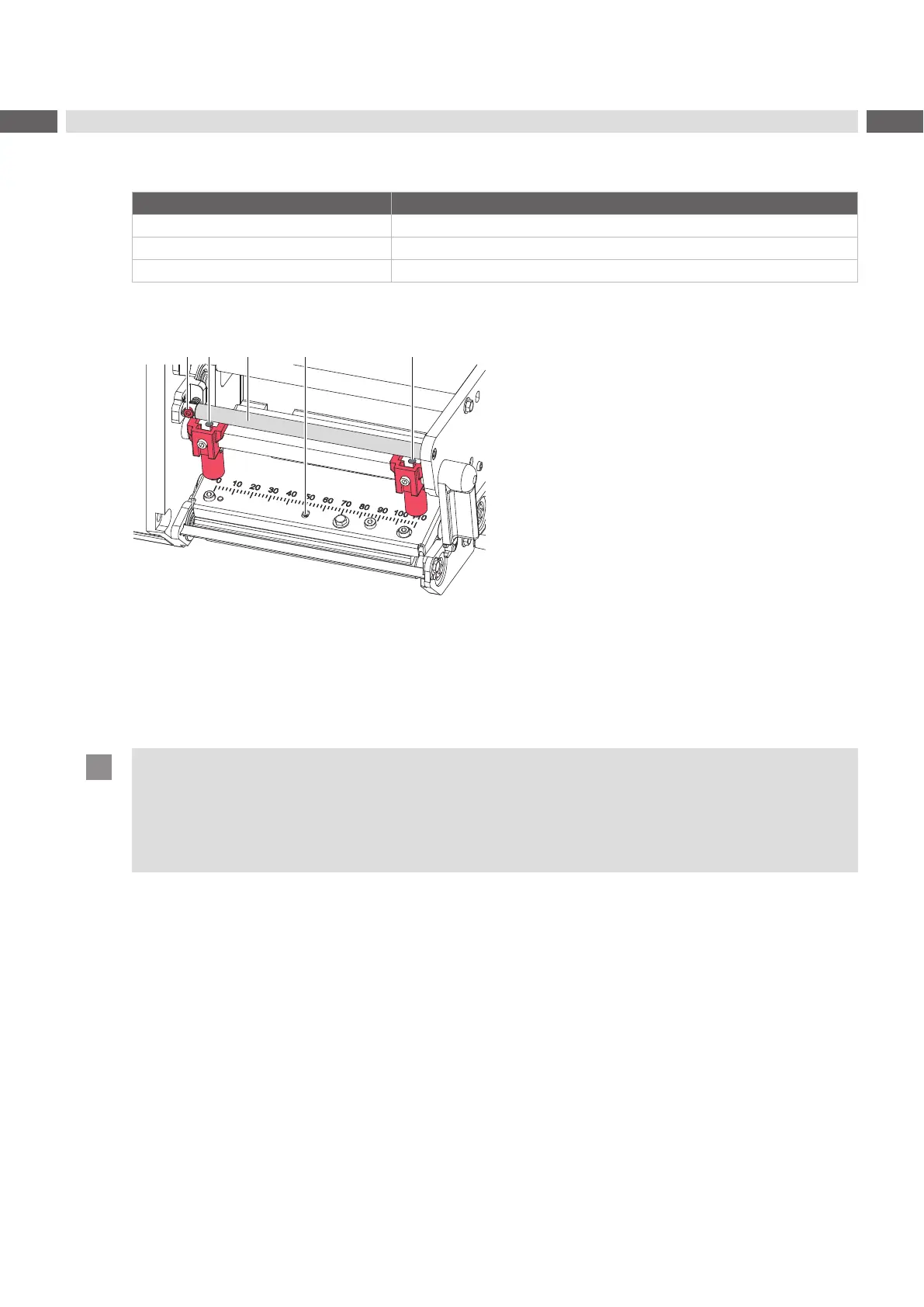
Figure 19 Adjusting the transfer ribbon feed path
Fine-tuning of the printhead pressure
If the ribbon shifts to one side in the print zone, turn the screw (2a) or (2b) on the opposite side clockwise in small
increments. Wait until the ribbon feed path has stabilized after each step of the adjustment.
Bowing the printhead
Attention!
The printhead assembly can be damaged when bowing the printhead.
Turning the adjustment screw (4) too hard can cause damage to the printhead assembly.
As soon as you perceive clear resistance when turning the adjustment screw (4), you may only continue
turning the screw in very small increments, but no more than one eighth of a turn.
Only turn the adjustment screw (4) as far as is absolutely necessary.
If the wrinkles cannot be remedied (e.g. wrinkles in the center), turn the adjustment screw (4) clockwise
with extreme care using an Allen key (1.5 mm) and observe the ribbon feed path.
When the adjustment screw (4) is tightened, the printhead is bent downward slightly in the center. It is possible
that a slight lightening at the edge areas of the print image could occur here.
If bowing is not necessary, turn the screw (4) clockwise until the screw is just barely clamping.
Adjusting the front transfer ribbon deection (3)
Turn screw (1) with Allen key and observe the behavior of the ribbon.
If wrinkles arise from the inner side turn the screw counterclockwise, if wrinkles arise from the outer side turn the
screw clockwise
5.2.6 Final Test
Recheck the setting with the test function Test grid ( Conguration Manual) or a similar print pattern.
When using standard cab media, the test printout must show lines with sharp contours and black areas without any
parts missing.
 Loading...