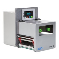
3
Table of Contents
1 Introduction ............................................................................................................................................ 4
1.1 Instructions ............................................................................................................................................... 4
1.2 General Safety Instructions ...................................................................................................................... 4
1.3 Protective Devices ................................................................................................................................... 5
1.4 Handling Electricity .................................................................................................................................. 5
1.5 Procedure in Case of Accidents .............................................................................................................. 5
1.6 Environment ............................................................................................................................................. 5
2 Preparation ............................................................................................................................................. 6
2.1 Tools ......................................................................................................................................................... 6
2.2 Removing and Installing the Rear Cover ................................................................................................. 6
3 Maintenance ........................................................................................................................................... 7
3.1 Cleaning by the Operator ......................................................................................................................... 7
3.2 Cleaning the Label Sensor ....................................................................................................................... 7
4 Replacing Assembly Units .................................................................................................................... 8
4.1 Replacing the Printhead ........................................................................................................................... 8
4.2 Replacing the Rollers and the Dispense Edge ....................................................................................... 10
4.3 Replacing the Slipping Clutches .............................................................................................................11
4.4 Replacing the Label Sensor ................................................................................................................... 13
4.5 Replacing the PCB CPU ........................................................................................................................ 14
4.6 Replacing the Power Supply Unit ........................................................................................................... 15
5 Adjustments ......................................................................................................................................... 16
5.1 Measuring and Adjusting the Winding Torques ...................................................................................... 16
5.1.1 Measuring the Winding Torques .......................................................................................................16
5.1.2 Adjusting the Winding Torques .........................................................................................................18
5.2 Adjusting the Printing Mechanism .......................................................................................................... 19
5.2.1 Preparing the Printer for Adjustment ................................................................................................ 19
5.2.2 Aligning the Printhead to the Print Roller.......................................................................................... 20
5.2.3 Adjusting the Printhead Pressure ..................................................................................................... 21
5.2.4 Adjusting the Distance of the Printhead from the Paper Guiding Edge ............................................ 21
5.2.5 Adjusting the Transfer Ribbon Feed Path......................................................................................... 22
5.2.6 Final Test .......................................................................................................................................... 22
5.3 Adjusting the Belt Tension at the Main Drive Motor ...............................................................................23
5.4 Adjusting the Head Switches ................................................................................................................. 24
5.5 Adjusting the Automatic Ribbon Saver ................................................................................................... 25
5.5.1 Setting the Eccentrics ....................................................................................................................... 25
5.5.2 Adjusting the Magnetic Clutch .......................................................................................................... 26
6 Troubleshooting and Error Treatment ................................................................................................ 27
6.1 Failure of Device Functions .................................................................................................................... 27
6.2 Permanent Hardware Faults .................................................................................................................. 27
7 Block Diagram ...................................................................................................................................... 28
8 Layout Diagram PCB CPU ................................................................................................................... 29
9 Index ...................................................................................................................................................... 30

 Loading...