1-6 Connecting the mixer systems
J-Type Revision J2005-2
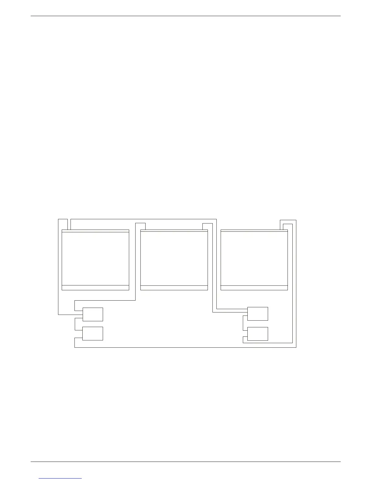
41618 0DLQ#DQG#H[WHQVLRQ#IUDPH#SRZHU#FRQQHFWLRQV
See fig 1-6 below for schematics of the frames power connections.
1. Using a short U-LINK cable (supplied), connect one of the outputs on the ±18V
PSU to one of the outputs on the +13V/+48V PSU in the “SYSTEM 1" power
supply rack. This operation “links” the d/c outputs on both power supply units in
the rack so that ±18V, +13V and +48V is available on all remaining output con-
nectors on either power unit.
2. Connect the second short “U-LINK” cable (supplied) between the ±18V PSU and
the +13V/+48V PSU’s in the “SYSTEM 2" power supply rack.
3. Connect a PSU cable between the “SYSTEM 1" rack and the “PSU SYSTEM 1"
connector on the MAIN FRAME.
4. Connect a PSU cable between the “SYSTEM 2" rack and the “PSU SYSTEM 2"
connector on the MAIN FRAME.
5. Connect a PSU cable between the “SYSTEM 1" rack and the “PSU SYSTEM 1"
connector on the EXTENSION FRAME 1.
6. Connect a PSU cable between the “SYSTEM 2" rack and the “PSU SYSTEM 2"
connector on the EXTENSION FRAME 1.
7. Repeat procedures 5. and 6. for EXTENSION FRAME 2 (a 3 frame console).
FIG 1-6. Power connections
368#6< 67 (0#4#+“4;9,
368#6<67 (0 #5#+“4;9,
368#6<67 (0 #4#+7;92.469,
368#6<67 (0 #5#+7;92.469,