Connecting the mixer systems 1-1
Revision J2005-2 J-Type
4 &RQQHFWLQJ#WKH#PL[HU#V\VWHPV
414 &RQVROH#PRGXODULW\
The J-Type was the first console to feature CADAC’s unique frame design which
allow users to put any module in any position, thus configuring the console to suit the
project in hand. Each module is fitted with XLR connectors and jack sockets on the
rear vertical face, enabling the module to be moved quickly and easily.
The J-Type module’s design features a motherboard, with plug-in daughter boards
for all audio and digital control functions. This ensures servicing simplicity and fast
replacement of any faulty component. Each module may be plugged into any posi-
tion in the console frame, by means of top quality two-part connector system, which
is designed as a mating pair to provide excellent mechanical and electrical reliability.
A rail system is used to guide each module into its correct position. Also, the console
design allows modules to be removed or inserted without powering down.
415 )UDPH#UHDU#FRQQH FWLR QV
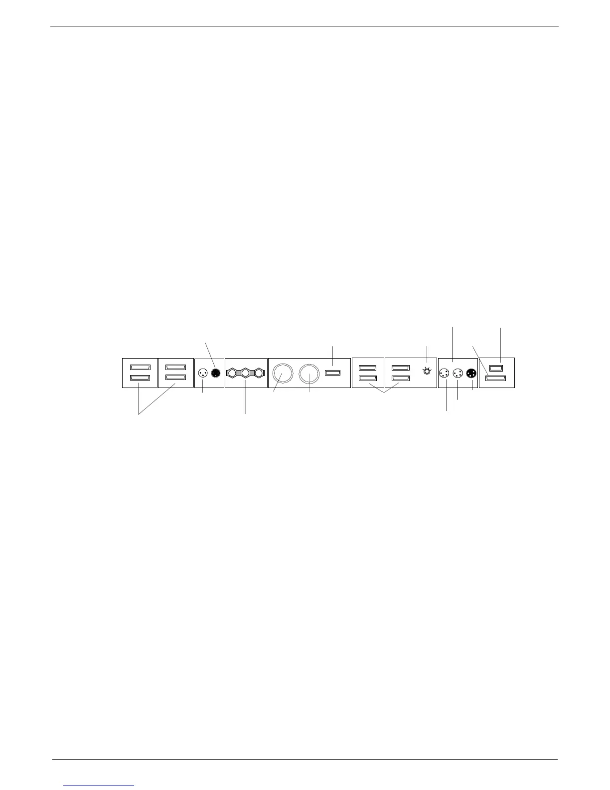
The connections on the J-Type console rear frame include the following (from left to
right):
■
■■
■
Audio Bus - frame to frame, up to 4 frames can be connected.
■
■■
■
PFL output to next frame.
■
■■
■
PFL input from module.
■
■■
■
Frame, GND and 0V-connections with grounding bar.
■
■■
■
PSU1 connector
■
■■
■
PSU2 connector
■
■■
■
Output for monitoring of PSUs
■
■■
■
Data Busses + Frame address selector
■
■■
■
Littlite input from PFL module.
■
■■
■
Littlite output to next frame.
■
■■
■
Littlite output to lights
■
■■
■
COMMS output
■
■■
■
Fader Bus
The use of these connectors is described in 1.3.5 Main and extension frame power
connections, 1.4 Connecting the console frames and 1.5 Connect Console Automa-
tion System.
4
56
7
4
5
6
7
$
%
$
%
Audio Bus - frame to
frame
From COMMS module
To next frame
Frame-GND-0
PSU 1 & PSU2
PSU Monitor
Data Bus
Selector - Frame Address
Console Littlites
To Lights
To Next frame
From COMMS module
COMMS
Fader Bus
FIG 1-1. Frame Rear Connections