7496 Dual Input Channel 3-21
Revision J2005-2 J-Type
to achieve the ‘null’ position. When the ‘null’ point is reached, both LEDs will turn
‘off’. Turning any pot will make it the current pot. Null LEDs are provided for Hz, Q,
Cut/Boost and Filters.
61518: 1XOO#/('V
Indicates fader/pot is in the programmed/correct position.
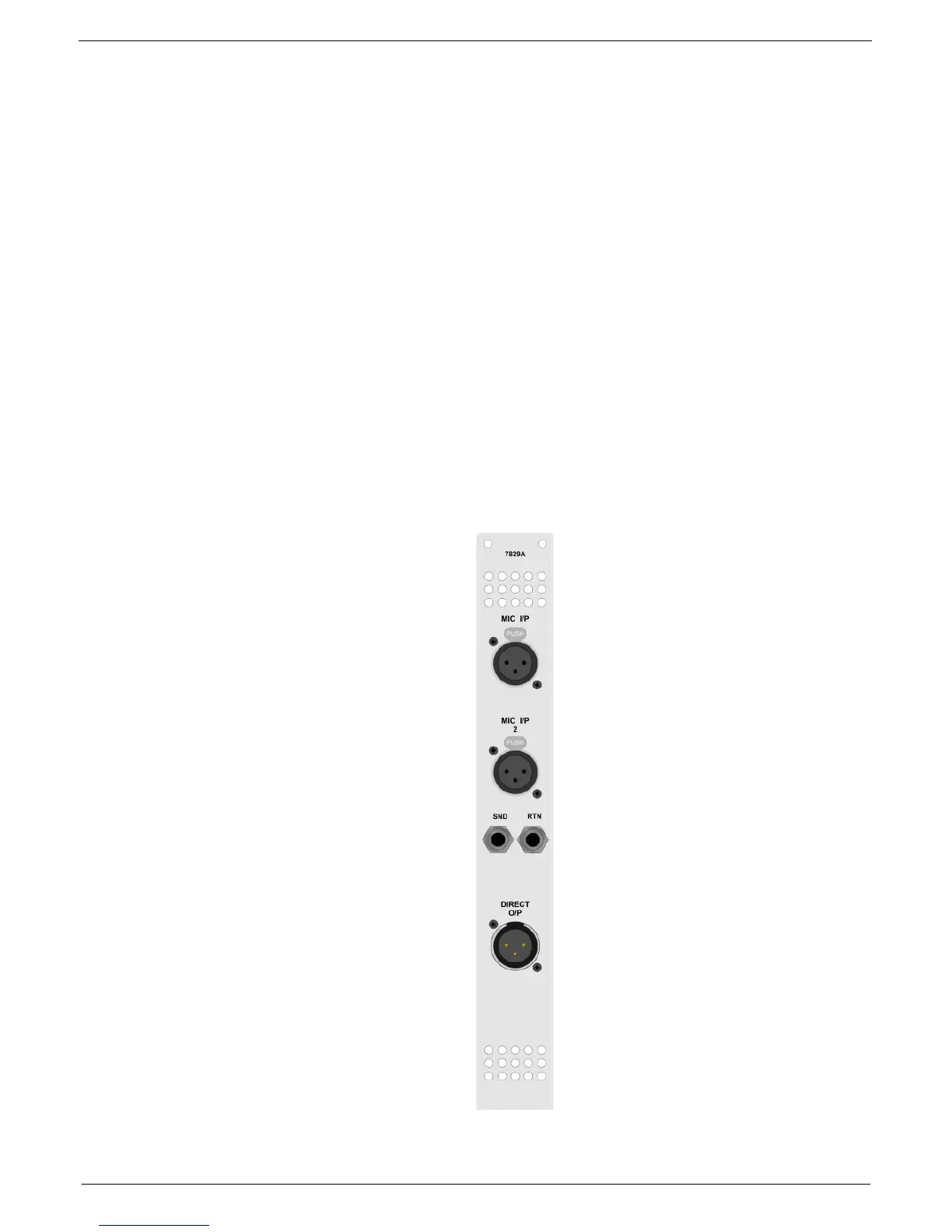
61518; 0RGXOH#5HDU#3DQHO#&RQQHFWRUV#:7<9
Inputs 1 and 2
Electronically balanced inputs on XLR 3-31 connectors for micro-
phone or line level sources.
Insert Send
Standard 0.25” (6.35 mm) TRS jack socket, providing continuous elec-
tronically balanced output.
Insert Return
Electronically balanced input on standard 0.25” (6.35 mm) TRS jack
socket that are switched into use when the “INS” switch is selected.
Direct Output
Balanced output from the module, delivered to an XLR 3-32 connec-
tor.
Important note:
Pin 1 on the XLR connectors and the ‘sleeve’ connections on the
jack sockets are connected to FRAME. This is to ensure that the console can comply
with the Electro Magnetic Compatibility (EMC) directive.
INPUT 1
INPUT 2
INSERT RETURN
DIRECT OUTPUT
INSERT SEND