Personal Ambulatory Oxygen System Provider Technical Manual
75
PN 20631679 Rev D
1.4 Unscrew the 2 Cooling Fan screws (PN: 6961-21-SEQ) holding the fan in place. Remove the Fan (PN: 1074-SEQ). Set aside for later
installation.
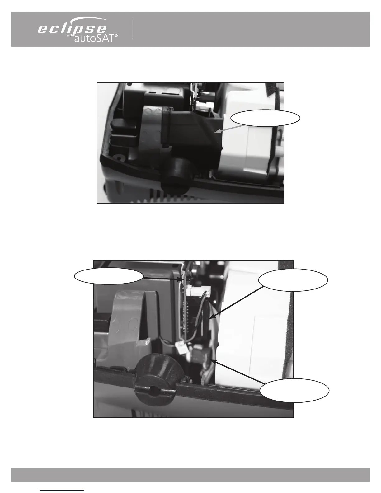
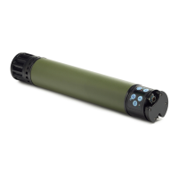
1.5 Remove the Exhaust tube in Figure 49. Set aside for later installation.
Fig 49: Exhaust Tube
1.6 Pull the Power Manager pcb 1” out of the case. Gently push the compressor box away from the Power Manager pcb about 1/8”.
Slide the board and the cabling out from under the edge of the compressor for better access. Disconnect the two wire harnesses (9V
batt & ATF harness) and the Control board ribbon cable shown in Fig 50. Remove the Power Manager pcb.
Fig 50: Wire harnesses and control board ribbon
Exhaust Tube
Control Board Ribbon
Cable
ATF Gearmotor
Harness
9 V Battery Harness