1 Installation instructions
Safety instructions
A+...
This device contains components that may generate
Lll
sparks or electric arcing!
Connecting the device
to
the power supply must comply with
the applicable national installation regulations!
This device contains components that may generate electric
arcing and sparks. Therefore when operating the device
in
a
garage or a similar location, it must
be
contained
in
a room or
housing designed for this purpose!
lf
the device
is
used
in
campers, caravans and boats, the
device and the battery must
be
installed apart
in
separate and
well-ventilated boxes!
The
installation and connection of electrical apparatus must
always
be
performed by appropriately trained personnel!
Always make sure that the power supply
is
disconnected!
Pull
out the mains plug!
When connecting the device, use only the supplied parts and
the specified cable cross-sections and fuses!
Only use suitable and undamaged tools!
Only connect the device according
to
the supplied connection
diagram!
Setting up
There are various accessory kits available that need
to
be
ordered separately.
Accessories
(not included)
Quick connector for battery "Quick power"
(part no. H 10 432 0110
00)
Temperature sensor for battery
II
(part no. H 10 012 0003
00)
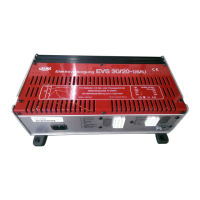
The
device should
be
set up
in
a location not exposed
to
hu-
midity and damp.
The
setting up location must
be
clean, dry
and well-ventilated. During operation, the housing may heat
up
to
approx. 75
°C.
Therefore maintain a minimum clear dis-
tance of 100
mm
and make sure that the ventilation slots
are
not covered.
The
installation space for the charger must
be
no
less
than
the dimensions given
as
follows, to ensure that a minimum
all-round distance of 100
mm
is
maintained.
Length: 502
mm/
Width: 373
mm/
Height: 245
mm
The
device should
be
placed
as
close
as
possible to the bat-
tery, but always
in
a separate box.
The
box for the battery
must have a ventilation hole facing towards the outside.
The
separate box for the device must
be
provided with ventila-
tion holes at the top and sides, with a total area of 100 cm
2
.
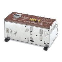
@ 29
Attach the device securely with the four fastening screws sup-
Line lengths and cross-sections
plied.
The
feet of the device
can
be
turned 90°.
To
do this, the
screws on the feet need to
be
unscrewed, then the feet can 6-pin connector
be
turned and tightened again when they are
in
position.
lmportant
Make sure that the ventilation slots remain unobstructed!
The
minimum clear distance must
be
100
mm
all around! lnsuffi-
cient ventilation can cause overheating of the device!
The
device
is
designed for operation
in
ambient temperatures
of up to 35
°C.
lf
the temperature inside the device rises due
to a lack of air circulation or due
to
high ambient temperature,
the charging current
is
automatically reduced
in
steps.
Connection
A+...
Disconnect the power cables from the battery and from
Lll
the mains before connecting or disconnecting any ca-
bles! Only use the specified cross-sections and fuses with the
correct rated current!
30 @
Circuit
12
V Consumer 1 - 3
Continuous current
Water pump
Refrigerator
12-pin connector
Circuit
Battery 1 positive terminal
Charging current line
red
Battery
II
positive terminal
Charging current line
red
Battery
II
negative terminal
Charging current line blue
Battery
II
positive terminal
Supply line
red
Measuring line D+ brown
Measuring line B+
red
Wire
cross-section
2.50
mm
2
min.
Line length
Wire
cross-
section
up
to
3 m
6mm
2
up
to
6 m 10
mm
2
over 6 m 16
mm
2
up
to
3 m 10 mm
2
over 3 m 16
mm
2
up
to
10 m 0.75
mm
2
 Loading...