Do you have a question about the Calira EVS 17/16-DS/IU and is the answer not in the manual?
Ensure secure placement, avoid tripping hazards, protect from moisture and flammable liquids.
Operate only undamaged devices, ensure safe cable positioning, use 30mA RCD.
Use device only for its specified purpose by the manufacturer.
Only use accessories and supplementary devices supplied or recommended by the manufacturer.
Do not charge 6V or non-rechargeable batteries; risk of explosive gas or housing rupture.
Describes the advanced technology, efficiency, and automatic charging features of the power supply.
Explains parallel and buffer operation where consumers can remain connected while the battery charges.
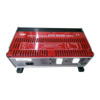
Identifies key components and data on the device top, including circuit breaker and technical specifications.
Details the fuses for various 12V user circuits like consumer, pump, and refrigerator.
Identifies the 230V AC input and output terminals on the device.
Lists the 12V DC outputs for consumers, including specific circuits and their connections.
Details the 12V DC inputs for connecting batteries, including sense and charging lines.
Describes connections for temperature sensors, control panels, and battery changeover switches.
Explains the 12V consumer outputs, their protection, and relay switching logic.
Describes the independent supply for heating and lighting, protected by a 10A fuse.
Details the water pump connection, its 5A fuse, and regulation via the control panel.
Explains absorber mode for refrigerators, powered by vehicle generator when engine is running.
Details the function of the temperature sensor for automatic charging voltage adjustment.
Explains the use of the switch for setting battery type (AGM/gel or liquid electrolyte) for charging.
Details the charging cycle for the supply battery (Battery 2), including Bulk, Absorption, and Float phases.
Explains how the starter battery (Battery 1) is charged in parallel during driving, mains, and solar operations.
Covers input voltage, output current, automatic charging phases, and temperature control.
Includes application types, operating temperature range, and cooling method.
Lists device dimensions, weight, test labelling, and intended use.
Warns about sparks, arcing, and requires compliance with regulations for installation and use.
Specifies requirements for installing in garages, rooms, or vehicles like campers and boats.
Emphasizes disconnecting power, using supplied parts, correct cables, fuses, and tools.
Defines HL (Bulk), NL (Absorption), and EL (Float) phases in the charging characteristic curve diagram.
Covers checking accessories, optional parts, and securing the device with screws.
Details requirements for location, ventilation, clearance, and enclosure to prevent overheating.
Emphasizes disconnecting power before connecting/disconnecting cables and using correct parts.
Describes preparing the connecting cable by removing insulation and ensuring proper fit.
Details how to attach the contact pin to the cable and crimp it securely.
Warns about loose connections causing shorts or fires.
Provides advice on increasing cross-section for longer cables and ensuring secure locking.
Shows the pinout for the 6-pole connector and its connections to consumers, pump, and refrigerator.
Illustrates the pinout for the 4-pole connector and its connections to consumers and permanent current.
Shows the contacts for the 12-pole connector and their arrangement for battery connections.
Illustrates the wiring diagram for connecting starter and supply batteries, including fuses and polarity.
Reminds to position fuses close to the positive poles of the batteries.
Lists the function of each contact on the 7-pole ribbon cable for the control panel.
Guides on connecting the temperature sensor cable to the device's 2-pin port.
Explains how to provide potential equalization using a green/yellow cable.
Details connecting the 230V output to the vehicle's distribution system and the earth circuit.
Describes connecting the mains input, ensuring the locking mechanism engages.
Covers initial operation, safety warnings for battery charging, and prerequisites for effective charging.
Explains the automatic charging process, parallel operation limits, ferry power, and generator use.
Provides a table listing common faults like device not working or battery not charging, with corresponding actions.
States that repairs or modifications should not be undertaken by users; only manufacturer or service personnel can repair.
Lists contact details for CALIRA Electronic GmbH & Co. KG, including address, phone, and fax.
Outlines warranty conditions, including proof of purchase, proper use, and no unauthorized modifications.
Advises that warranty claims should include a detailed fault description for faster processing.
| Brand | Calira |
|---|---|
| Model | EVS 17/16-DS/IU |
| Category | Power Supply |
| Language | English |