Do you have a question about the Calira EVS 38/20-DS/IU and is the answer not in the manual?
Ensure secure placement, cable routing, and environmental protection for safe operation.
Operate only undamaged devices and ensure safe cable positioning to prevent shocks.
Use devices only for manufacturer-specified purposes to ensure safety and functionality.
Use only manufacturer-supplied or recommended accessories to avoid hazards.
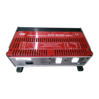
Combination charger/separator for 12V lead batteries, suitable for mobile homes.
Do not use with 6V or non-rechargeable batteries due to explosion risk.
Microprocessor-controlled switched-mode technology for high output, efficiency, and battery protection.
Details about the six flat plug-in fuses for 12V user circuits.
Information on the 230V mains protection circuit breaker.
Electronic protection, voltage monitoring, and charging phases.
Charging via generator during driving, parallel with supply battery.
Outputs controlled by bistable user relay, protected by 10A fuses.
For heating and light, protected by 7.5A fuse, independent of user relay.
Activated by control board switch, protected by 5A fuse.
Changeover switch for absorber or compressor modes.
Prevents freezing at low temperatures, protected by 5A fuse.
Alternating voltage 230V/50Hz, range 195-265V.
Max 20A charging current for battery II, compensating for battery I.
Details on main, post, and holding charge phase switching criteria.
Relay capacities for Tremat, refrigerator, and user circuits.
Ambient -25°C to +35°C, housing may reach 75°C; cooling by convection.
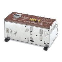
For 12V batteries (70-200Ah) and current distribution, aluminium housing.
Schematic diagram showing main, post, and holding charge phases.
Warnings about sparks, arcing, and handling by qualified personnel.
Comply with regulations, ensure separation in vehicles, use qualified personnel.
Disconnect power, use supplied parts, correct cross-sections and fuses.
Clean, dry, ventilated location, minimum 100mm clearance.
Ensure unobstructed ventilation slots to prevent overheating.
Securely attach with screws, adjust legs by loosening bolts.
Recommended lengths and cross-sections for battery cables.
Disconnect battery and mains before connecting/disconnecting.
Connecting the 12-pole flat plug to the control panel.
Terminal assignments for the 12-pole connector.
Terminal assignments for the 7-pole connector.
Connecting the 5-pole flat cable to the fresh water tank.
Connecting the 2-pole flat cable to the waste water tank.
Fastening and connecting the temperature sensor to battery II.
Connecting 12-pole plug to supply and starter batteries.
Method for handling cage tension spring clamps for connection.
Connecting positive cable to contacts 16-22, requires 40A fuse.
Connecting positive cable to contacts 26-27, requires 40A fuse.
Schematic showing connections for battery I and II, fuses, and cable cross-sections.
Connection of the lower wiring loom to the A01 plug.
Connection of the upper wiring loom to the 12-pole A02 plug.
Using a green/yellow cable for potential equalisation.
Connecting 230V outputs to the mains system of the vehicle.
Device is operational when connected to mains; disconnect before DC connections.
Warnings about charging batteries with short-circuited cells.
Automatic charging, phases, and parallel operation current limits.
Always disconnect from mains before performing maintenance.
Clean device and ventilation slots with a dry, lint-free cloth.
Check connections, polarity, fuses, and mains connection.
Start motor, check voltage rise above 1.5V for charging.
Check fuses for charging issues during driving.
Ensure better ventilation if the device overheats.
Procedures for when none of the listed faults apply.
Do not undertake repairs; only manufacturer or service personnel can repair.
Two-year warranty for material/manufacturing defects with conditions.
Provide fault description; cannot accept items sent without paid postage.
| Input Voltage | 230 V AC |
|---|---|
| Output Voltage | 12 V DC |
| Output Current | 20 A |
| Charging Characteristic | IUoU |
| Input Frequency | 50/60 Hz |
| Protection Class | II |
| Cooling | Convection |
| Safety Standards | EN 60335-1, EN 60335-2-29 |
| EMC Standards | EN 61000-3-2, EN 61000-3-3 |