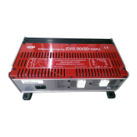
Do you have a question about the Calira EVS 17/07-DS/IU and is the answer not in the manual?
Ensure secure placement, cable routing, and avoid hazardous environments.
Operate with undamaged housing/cables and ensure safe cable positioning.
Use device only for its intended purpose as specified by the manufacturer.
Use only manufacturer-supplied or recommended accessories for safety.
Automatic charger/separator for 12V lead batteries in caravans and mobile homes.
Do not charge 6V, non-rechargeable, or NiCd batteries; avoid damp/flammable environments.
Utilizes microprocessor-controlled technology for high output, efficiency, and battery protection.
Supports parallel and buffer operation, allowing continuous consumer connection.
Automatically adjusts charging voltage based on battery temperature for optimal performance.
Reduces charging current automatically if internal temperature rises due to poor circulation or ambient heat.
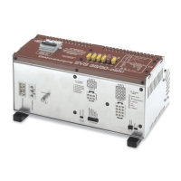
Illustration of the device's top-side components and connections.
Details the 12V user circuit fuses and their ratings for different circuits.
Shows the 230 Volt circuit breaker for mains input protection.
Identifies all input/output ports on the front of the device with numbered labels.
Describes the 12V outputs, their wiring, and fuse protection.
Explains the circuit for heating and immediate light, its connection, and fuse.
Details the water pump circuit, its regulation, and fuse.
Explains absorber and compressor modes for refrigerator operation.
Describes the function of the battery changeover switch for AGM/gel or liquid batteries.
Charges with max current until battery reaches 14.4V; monitors voltage and current.
Maintains 14.4V for a set duration for AGM/gel or liquid batteries.
Maintains 13.8V, providing minimal current for battery equalization.
In parallel or holding charge, consumed current is immediately recharged.
Charges starter battery via vehicle generator during driving.
Charges supply battery first, then starter battery from mains power.
Charges starter battery via solar panels when supply battery reaches 14.1V.
Details AC input, DC output, charging current, and automatic switching parameters.
Explains how temperature sensor input affects charging voltage thresholds.
Specifies operational modes, ambient temperature limits, and cooling method.
Covers implementation regulations and test labeling (CE mark).
Lists the device's housing material, dimensions, and weight.
Refers to a schematic diagram illustrating the charging phases and voltage/current profiles.
Warns about sparks, arcing, and stresses compliance with regulations and qualified personnel.
Highlights requirements for garages and mobile homes, including ventilation and separation.
Specifies clean, dry, well-ventilated locations and minimum clearances for heat dissipation.
Details securely attaching the device and ensuring ventilation slots remain unobstructed.
Specifies required wire cross-sections for 4-pole, 6-pole, and 12-pole plug connectors.
Advises on preparing cables for plug connectors and using specified cross-sections.
Details removing insulation and preparing cable ends for contact pins.
Describes the process of attaching contact pins to cables using crimping pliers.
Emphasizes secure attachment of pins to prevent short circuits and fires.
Shows pin assignments for the 6-pole connector and its connection to users.
Explains how to insert, lock, and withdraw the 6-pole connector securely.
Shows pin assignments for the 4-pole connector and its connection to consumers.
Stresses ensuring contact pins engage securely to prevent malfunctions.
Illustrates pin assignments for the 12-pole connector for battery connections.
Instructs to position fuses close to the positive battery terminals for safety.
Details the 7-pole ribbon cable connections for the control panel and their functions.
Explains how to connect the temperature sensor cable to the device's dedicated port.
Instructions for providing potential equalization using a green/yellow cable for safety.
Describes connecting the 230V input and output to the vehicle's electrical system and securing connections.
Outlines connecting to mains, switching off DC before connections, and operational status.
Lists requirements for battery voltage (12V) and capacity (min 60Ah) for proper charging.
Explains the automatic main, post, and holding charge phases based on battery voltage.
Advises against connecting the device to power supplies on ferries due to voltage variations.
Advises operating generators within 230V parameters and connecting/disconnecting safely to avoid spikes.
Recommends cleaning the device and ventilation slots with a dry, lint-free cloth.
Check circuit breaker and mains connection if the device is not functioning.
Verify battery connection, polarity, and re-seat the mains plug.
Check fuses and connections to the affected 12V circuits.
If overheating occurs, wait for the device to cool down after thermal switch activation.
Contact the manufacturer if the device does not work and the fault is not listed.
Do not attempt any repairs or modifications; only manufacturer or service personnel should service the device.
Guarantee covers statutory provisions, starting from purchase date, with conditions like proof of purchase.
Claims require detailed fault description, proof of purchase, and adherence to specified use.
| Input Voltage | 230V AC |
|---|---|
| Output Voltage | 12V DC |
| Output Current | 17A |
| Charging Characteristic | IUoU |
| Frequency | 50/60Hz |
| Protection | Short Circuit |
| Operating Temperature | 0°C to 40°C |


 Loading...